Showing posts with label process control. Show all posts

Get To Know MS Jacobs & Associates for Industrial Process Control Instruments and Equipment

Electric power generation plant
MS Jacobs serves the electric power generation industry,
as well as chemical, oil and gas, water and wastewater
M.S. Jacobs and Associates has been a leading manufacturer's representative and distributor of industrial instrumentation and controls since 1945.  Expanding from its original focus on the steel industry, MS Jacobs services and supplies products in all major industrial markets, including power generation, chemical processing, pulp and paper, oil and gas production, water and wastewater treatment, and nuclear power generation.

The company's longevity and dedication to the industrial market has resulted in a broad offering of superior quality products for flow, level, pressure, and temperature measurement, as well as filtration products and valves. Everyone at MS Jacobs takes pride in the company's ability to solve tough applications and provide exceptional customer service with a team of trained outside sales engineers and inside customer service representatives.

MS Jacobs' Pittsburgh service center provides instrument calibration and repair for MSJ's complete line of products, as well as those of other manufacturers. The company carries factory authorization for repair of numerous manufacturers' industrial process instrumentation products. The service center also provides custom assembly of instruments and other gear to meet customer requirements. Completed assemblies are tested and certified prior to shipment.

Reach out to MS Jacobs & Associates for the products and services that move your process instrumentation and control projects toward a successful completion.


Oxygen or High Purity Service Valve Preparation

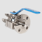
cutaway view of industrial ball valve for process control
Industrial Ball Valve
Courtesy Marwin Valve
Oxygen is used extensively throughout a wide range of industrial processes. Medical, deep-sea, metal cutting, welding, and metal hardening are a few examples. The steel industry uses oxygen to increase capacity and efficiency in furnaces. As a synthesis gas, oxygen is also used in the production of gasoline, methanol and ammonia.

Odorless and colorless, oxygen is concentrated in atmospheric air at approximately 21%. While O2, by itself, is non-flammable, it vigorously supports combustion of other materials. Allowing oils or greases to contact high concentrations of oxygen can result in ignition and possibly explosion. Oxygen service preparation of an industrial valve calls for special cleaning processes or steps that remove all traces of oils and other contaminants from the valve to prepare for safe use with oxygen (O2). Aside from the reactive concerns surrounding oxygen, O2 preparation is also used for applications where high purity must be maintained and valves must be free of contaminants.

Gaseous oxygen is noncorrosive and may be used with a variety of metals. Stainless steel, bronze and brass are common. Liquid oxygen presents unique challenges due to cryogenic temperatures. In this case, valve bodies, stems, seals and packing must be carefully chosen.

Various types of valves are available for oxygen service, along with a wide array of connections, including screwed, socket weld, ANSI Class 150 and ANSI Class 300, DIN PN16 and DIN PN40 flanged ends. Body materials include 316 stainless steel, monel, bronze and brass. Ball and stem material is often 316 stainless steel or brass. PTFE or glass filled PTFE are inert in oxygen, serving as a common seat and seal material employed for O2 service.

Common procedures for O2 service are to carefully deburr metal parts, then meticulously clean to remove all traces of oil, grease and hydrocarbons before assembly. Valve assembly is performed in a clean area using special gloves to assure no grease or dust contaminates the valve. Lubricants compatible with oxygen must be used. Seating and leakage pressure tests are conducted in the clean area, using grease free nitrogen. Specially cleaned tools are used throughout the process. Once assembled, the valves are tested and left in the open position. A silicone desiccant pack is usually inserted in the open valve port, then the valve ports are capped. A warning label about the desiccant pack's location is included, with a second tag indicating the valve has been specially prepared for oxygen service. Finally, valves are individually sealed in polyethylene bags for shipment and storage. Different manufacturers may follow slightly differing protocols, but the basics are the same. The valve must be delivered scrupulously contaminant free.

The O2 preparation of valves is one of many special production variants available to accommodate your special application requirements. Share your valve requirements and challenges with a valve specialist to get the best solution recommendations.

Video Reenactment and Analysis of Industrial Fire and Explosion

outdoor petroleum storage tanks at industrial facility
All facilities have some element of risk
Industrial accidents range in severity and impact from minuscule to catastrophic. As operators, owners, or technicians involved with industrial operations, we all have a degree of moral, ethical, and legal responsibility to conduct our work in a manner that does not unduly endanger personnel, property, or the environment. Maintaining a diligent safety stance can be helped by reviewing industrial accidents at other facilities. There is much to learn from these unfortunate events, even when they happen in an industry that may seem somewhat removed from your own.

The U.S. Chemical Safety Board, or CSB, is an independent federal agency that investigates industrial chemical accidents. Below, find one of their video reenactments of an explosion that occurred in Texas in 2013, along with their findings regarding the cause of the incident. Check out the video and sharpen your senses to evaluate potential trouble spots in your own operation.

Contact M.S. Jacobs & Associates for any safety related information you may need concerning their lines of industrial and process control products.


New Product: Non-Contact Radar Level Transmitter

non-contact radar level transmitter for industrial process measurement and control
Model R96
Non-Contact Radar Level Transmitter
Courtesy Magnetrol
A new entry into the non-contact radar level measurement transmitter arena has been released by Magnetrol, a well known manufacturer of level and flow measurement instrumentation for the industrial process control field. The new Model R96 Non-Contact Radar Level Transmitter is intended primarily for applications where continuous fluid level measurement is required.

The company sums up the technical capabilities with their description of the product...

"Virtually unaffected by the presence of vapors or air movement within a vessel’s free space, the two-wire, loop-powered, 6 GHz Radar transmitter measures a wide variety of liquid media in process conditions ranging from calm product surfaces and water-based media to turbulent surfaces and aggressive hydrocarbon media."

The Model R96 level transmitter offers features that combine to deliver a state-of-art instrument for accurate continuous level measurement. A product brochure is included below. Contact application specialists to formulate the right product configuration for your level measurement challenge, or to get more detailed information.


Orion Instruments Announces New Level Transmitter

Direct insertion and external mount versions of
Orion JM4 Magnetostrictive Level Transmitter
Courtesy Orion Instruments
Orion Instruments, a world class manufacturer of magnetic level indicators, level switches, and level transmitters, has released a new product for use in the industrial process measurement and control field. Their Jupiter Model JM4 magnetostrictive transmitter incorporates the company's many years of research, development, and field experience to provide a safer, simpler, and smarter transmitter for liquid level measurement and control.

The new model from Orion boasts level measurements with accuracy as high is +/-0.05" (1.27mm). The transmitter head can be rotated up to 310 degrees with an option for remote mounting. Variants are available for direct insertion or external mounting, with approvals for a number of area classifications. There are other valuable features to this series of level measurement instruments that reflect Orion's expertise in the field.

Browse the new product brochure included below. It provides illustrations of the product and its operating principle, along with dimensioned drawings and a listing of all the product options and variants. You can always obtain whatever information you need about Orion level measurement instruments from a product specialist. Share your liquid level measurement challenges and requirements with them for recommendations on the best solutions.


Knowledge Base and Selection Guide For Magnetic Level Indicators

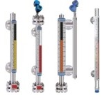
Orion Instruments Magnetic Level Indicators
Magnetic Level Indicators
Courtesy Orion Instruments
Industrial process control frequently involves the storage of liquid in vessels or tanks. Continuous and accurate indication of liquid level within the tank is an essential data point for safety and process management. While there are a number of methods and instrument types utilized to provide tank level measurement, the instrument of choice is often a magnetic level indicator, also referred to as a magnetic level gauge. Its use for providing level indication has a number of positive attributes:
  • Construction that is resistant to breakage.
  • Measuring indicators, switches, and transmitters mounted externally, without contacting the medium being measured.
  • Maintenance free operation. No regular cleaning needed.
  • Readable level indication from greater distance than glass sight gauges.
  • Magnetic level indicators can accommodate greater fluid level ranges without the need for multiple instruments.
Orion Instruments, a Magnetrol company and industry leader, has produced a comprehensive guide to magnetic level gauges, switches, transmitters, and related products. It delivers experts and newcomers an understandable and clear description of the technology and principals of operation behind magnetic level gauges and instruments. The guide also assists the reader in properly specifying and selecting the best instrument configuration for an application. A table of contents at the front of the document helps readers to quickly find the information they need.

Take a couple minutes to roll through the document and you are likely to find new and useful application tips and product information. Any questions about magnetic level indicators or your process measurement and control applications can be clearly addressed by a product specialist.


Filtration Yields Returns By Protecting Fluid Process Lines and Equipment

Dual basket strainer with changeover valve
Duplex Basket Strainer With Diverter Valve
Courtesy Eaton Filtration
Most people think of "industrial" equipment as super heavy duty, virtually indestructible. Those of us responsible for operating and maintaining industrial process equipment recognize that is not the case. Even the most formidable appearing equipment can be crippled if not protected from the insidious effects of particulates.

There are numerous strategies for mediating the impact of particulates on industrial fluid process equipment and systems. The best solutions will be customized for each process, with consideration given to:
  • Maximum particle diameter threshold: At some level, particulates may be small enough to preclude damage to the system. Above the threshold level, removal of the particles brings some benefit to process operation.
  • Pressure drop associated with any mitigation techniques: Assuming that mitigation will involve the addition of components to the fluid system, minimizing the added pressure drop is advantageous.
  • Overall volume of particulate matter to be removed: Most often, mitigation equipment traps and retains particulate matter. The retaining capacity of the unit must match the particulate production rate of the process. Be mindful that certain events, such as routine maintenance or cleaning of process equipment, may produce surges of particulates in some types of systems.
  • Location of the filtration equipment: Filtration units must be placed in the process flow upstream of the equipment or system portion to be protected. An additional consideration is a provision for maintenance through placement in a convenient, easily accessible location.
  • Filtration equipment materials of construction: The filtration gear must be fabricated of materials compatible with the process media.
I have provided a data sheet below with cutaway illustrations and detailed performance data for one type of filtration unit. This particular equipment is manufactured by the filtration division of Eaton and features a duplex strainer basket arrangement with a diverter valve. The process fluid flows through one strainer, with the other clean and ready to be brought on line when the active basket becomes clogged. When the active basket becomes clogged and pressure drop excessive, the operator moves a lever to divert the flow to the second basket, sealing off the now clogged basket area so that it can be opened and cleaned. This design provides for uninterrupted process operation.

Browse the provided data sheet. You will likely pick up something you did not already know, or get a quick refresh of your technical knowledge. The duplex basket strainer is one type in a wide variety of filtration products available for every conceivable process application. Share your challenges with a product specialist. Combining your process knowledge and experience with their thorough product application expertise will generate great solutions.


Innovations In RTD Signal Conditioning - One Manufacturer's Compilation

Industrial process measurement and control RTD signal conditioner
RTD Signal Conditioning Units
Courtesy Acromag
Temperature measurement may be one of the oldest components of process control and laboratory research. The measurement of temperature has progressed through a variety of methodologies, some of which are still in use today. Modern industrial process control relies heavily on the use of RTDs (resistance temperature detector) for their accuracy and stability.

Some of us have used RTDs in our process designs for many years, maybe without recognizing the innovations that have come about in the signal conditioning portion of our installations. One manufacturer of industrial signal conditioning equipment, Acromag, has compiled the ten most significant recent advances in RTD signal conditioning. I have included their white paper below.

Browse the paper, as it is brief and informative. You will likely see a few improvements of which you were unaware. Share your temperature measurement and signal conditioning challenges with an application specialist. Combining your process experience with their product application expertise will produce positive solutions.


Ethernet I/O Modules Provide Connectivity Advantages

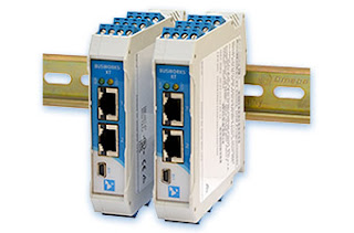
Industrial Ethernet Input and Output Modules on DIN Rail
Industrial Ethernet I/O Modules
Courtesy Acromag
Industrial process control relies on the accurate and timely delivery of process measurements and data to the point of control and decision making. As technology affords more opportunities to measure and transmit process variables, the demand for incorporating the additional information in the control and decision making process expands. The frequency at which data can flow from a process has also increased dramatically, and there is often significant value derived from rapid sampling. Transmitting the voluminous measurement data to the point of control can be accomplished using three basic methods:

  • Point to point wiring from each measurement device to the control point.
  • Wireless linkup from measurement location to controller.
  • Wired network connection between measurement and control devices.
Each of these connection topologies has particular attributes which may better suit a particular application.  For a wired network scheme, Acromag has designed a line of I/O modules that make installation and configuration a smooth operation. Helpful features include:
  • Power wiring options that allow back connected bus power or top mounted screw terminals. You can even provide primary and backup power sources to the two connections.
  • Front facing screw terminals for connections make status checking of inputs a simple operation with your digital volt meter.
  • Modules are rail mounted and can be placed immediately adjacent to one another for high density installation.
  • Modules have a built in webpage for display of operational information. Configuration is accomplished using a front mounted USB port.
  • Operable in temperatures -40 to +70 deg. Celsius.
  • Two Ethernet ports on each unit allow modules to be daisy chained, reducing or negating need for local hubs.
  • Acromag's Priority Channel Technology assures that data update frequencies are maintained, regardless of other network traffic.
The short video below provides additional detail on the useful features of the Acromag line of industrial Ethernet I/O modules. Watch the video. Share your process measurement and control connectivity challenges with a sales engineer specializing in industrial Ethernet I/O. Combine your process knowledge with the state of the art product knowledge of a product specialist for the best solutions.


Industrial I/O Applications Compilation Provides Answers

Process Measurement and Control Input and Output Devices
Process Measurement and Control I/O Devices
Courtesy Acromag
Process measurement always presents two basic challenges, derive a measured value of the process condition, then transmit or deliver that value to a recording or decision making device. Your knowledge and ingenuity applied to the design and implementation of these measurement and transmission functions are the key to how effectively your control system will function. Acromag, a world class manufacturer of signal conditioning equipment and industrial I/O devices, has produced a compilation of applications that illustrate some creative and best practices for establishing effective connections between control and measurement devices. The applications are drawn from defense, power generation, and manufacturing, but the knowledge shared can be broadly applied to many industries.

Look through the applications and you will find something of value. You can always contact a product and application specialist to discuss your process measurement and control challenges and requirements. Combining their product application expertise with your process knowledge will generate the best solutions.


Application Suitability of Ultrasonic Flowmeters

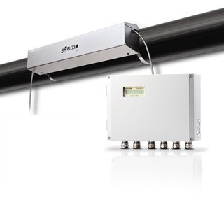
Ultrasonic Liquid Flow Meter
Ultrasonic Liquid Flow Measurement System
Courtesy Flexim America
Industrial process control frequently requires the accurate measurement of fluid flow. There are several widely applied methods for measuring flow, each having particular advantages which may apply to a specific application.

Ultrasonic flow meters measure flow indirectly by calculating transit time of a sound wave through, or reflecting from, a flowing fluid. The velocity of the fluid has an impact on the transit time, from which a flow rate can be calculated. Attributes of ultrasonic flow measurement that may determine suitability for a particular application include:

  • Transducers can be clamped on exterior pipe surface where measurement is needed.
  • Non intrusive measurement technology prevents contact between media and measuring elements.
  • No significant pressure drop associated with measuring device installation.
  • Reduced leak potential.
  • No moving parts.
  • Comparatively higher cost than some other technologies.
  • Fluid characteristics must be well known for proper application.
  • Pipe cross section must be completely filled by media to acquire accurate flow measurement.
Learn more about this process measurement and control technology in the product detail sheet below. Consult with a product application specialist for more detailed product information and tips on how to best apply ultrasonic flow meters to your process.


Avoid Process Downtime With Five Device Protection Considerations

Industrial Process Instruments
Industrial process control is everywhere. Sometimes it is dangerous or complex. In other cases it may be relatively mundane. In all industrial processes, though, maintaining operation is key. Stakeholders rely on the process output and look to the designers, engineers, and operators to deliver, in many cases, uninterrupted performance. The world is a place of many uncertainties, some of which can impact your process in undesirable ways. While it's not practical to design or build to accommodate every possible adverse event, application of experience and good judgement in a few areas may significantly shorten the list of things that can negatively impact your process.

Process control is achieved through the measurement of various conditions and application of regulated adjustments to the process inputs to deliver a desired output. Process variable measurement serves as the input to the control system. In the industrial sphere, it is common to see devices used for the measurement and transmission of temperature, pressure, flow, mass, level, and electrical parameters like voltage, current, capacitance and more. Regardless of what is being measured, there are three common characteristics:

  • Device - A combination of a sensor and a translator that together detect some physical condition of the process and produce an output signal that can be correlated to the process condition. 
  • Location - The device will have a location that is dictated by the process construction and arrangement. Device locations have a tendency to be inflexible.
  • Signal transmission path - Unless the control element is integral to, or adjacent to, the measurement device, there will be some path over which the measurement signal must travel to reach an associated control element. 

Looking at these three elements for each measurement point, consider the five risk categories below in evaluating what you can do to safeguard your process measurement instrumentation. It's advisable to open a conversation with an experienced application specialist and freely discuss your concerns. Gathering additional input from various experienced sources will help you determine how extensive your protective measures should be to deliver a balance between cost and the probability of certain adverse events.

  • Local Weather: There is local weather data available for almost every place on the planet. Take the time to procure reliable data and examine the distribution of temperature, humidity, precipitation, and wind conditions throughout all seasons. Clearly, if portions of the process are located outdoors, extreme local weather conditions will need to be accommodated. Even if your process is located indoors, local weather information is important if the process is to operate continuously. Consider whether an indoor process must continue to operate, even if the building HVAC system fails and indoor conditions begin to be impacted by outdoor conditions. Also, depending upon the design of the building climate control system, changing outdoor conditions can have a noticeable and possibly significant impact on the indoor air conditions.
  • Process Generated Conditions: There may be specific aspects of your process that produce occurrences of vibration, pressure spike, electrical interference, or a host of other aberrations that may affect the proper operation of measurement devices. Know your process....really know it. Protect instrument sensors from potentially damaging transients and other process conditions that can be reasonably expected to occur. Device location relative to sources of electrical interference, elevated temperature, vibration, shock, and other transient conditions should be considered.
  • Security: Your design goal should be to achieve a very high level of certainty that the signals generated by the measurement devices are uninterrupted and reflect the actual process conditions. There are two cases I always consider for security. The first is cyber, which applies in the case of a process measurement device network connection. Necessary steps should be taken to thwart an attempt to breach the network and detect unusual conditions that might indicate an invader's attempt to manipulate the process. My second case is related to device access by those without proper knowledge, training, or permission. Protection from these threats will likely involve a combination of physical barriers and procedures.
  • Physical Contact: Industrial settings are, well, industrial. Large, heavy, irregular, unwieldy, and sharp things can sometimes be moved through areas occupied by process measurement gear. Technicians with carts, tools, and materials frequently pass through process areas to do their work. Protecting equipment and instruments from damaging contact pays dividends for the life of the installation. Consider, in your design and layout, the proximity of instruments to areas of traffic. If applicable, also consider areas overhead. The level of protection will need to be balanced with the need for access by qualified individuals for service, maintenance, calibration, and observation, as applicable.
  • Moisture: Electronics are a mainstay of modern measurement instrumentation. Clearly, liquid moisture must be kept from contact with electronic circuits. Vaporous moisture will find a path to the internals of your electronic devices. This vapor, which is present in considerable levels in almost every indoor and outdoor environment, can condense when the right conditions are present. It is imperative that enclosures, conduit, boxes, fittings must be provided with barriers to moisture entry and/or a reliable means to automatically discharge accumulated liquid moisture before damage occurs.
There is much to think about in the realm of device protection. Balancing the costs of protection, the impact of protective measures on the ability to service and operate the process, and the risk involved with process failure or shutdown requires the application of technical expertise, experience, and sound practical judgement. Draw information and opinion from multiple sources, including sales engineers. Combine their product application knowledge with your process expertise to make good decisions.


Are You Well Grounded on Grounding? - Part 3

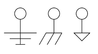
Drawing symbols for Electrical Ground
Electrical Drawing Symbols for Ground
Welcome to the third and final part of this series on electrical grounding for equipment and instruments. Part One and Part Two can be found as previous posts to this blog, and I hope you read them too. Those initial parts provided practical knowledge about equipment grounding and personnel protection in a format understandable to anyone. Those of us more deeply involved with electrical matters likely know someone that could benefit from these articles and I urge you to share.

The white paper that I have included below was produced by the folks at Acromag, a world class manufacturer of signal conditioners and other industrial I/O devices. They have done a fantastic job of presenting technical subject matter in a compact and very understandable form. The subjects covered in the series include:
  • Ground as protection
  • How a ground fault circuit interrupter (GFCI) works
  • Ground as a voltage stabilizer and transient limiter
  • Tips on improving safety and signal integrity
  • The importance of circuit grounding
  • Description of the US AC power system and its use of earth ground
This third installment includes a section entitled "Some Basic Ground Rules For Wired Equipment" which lists out an array of useful tips for connecting wired signals to devices, and more.

Product specialists are always on hand to discuss and solve your process measurement and control issues. Combine the process knowledge of the on site stakeholder with the product and application expertise of the professional sales engineer to produce the best outcomes.


Are You Well Grounded on Grounding? - Part 1

Ground Symbols
Some Drawing Symbols Used For Ground
Grounding of electrical equipment and electronic instrumentation is an aspect of project design and implementation that sometimes gets taken for granted. To say that proper electrical grounding is important is an understatement because, without it, certain safety aspects that we rely upon will simply not work. Additionally, and often more confounding, is the intermittent, unexpected, or bizarre behavior of electronic measurement and control devices when proper electrical grounding is not established.

I came across a series of white papers written by some knowledgeable people at Acromag, a manufacturer of industrial input and output devices (industrial I/O). The comprehensive three part series covers best practices involved in the grounding of electrical equipment and electronic instrumentation, in language understandable to a reader of any technical level. The subject matter includes:

  • Ground as protection
  • How a ground fault circuit interrupter (GFCI) works
  • Ground as a voltage stabilizer and transient limiter
  • Tips on improving safety and signal integrity
  • The importance of circuit grounding
  • Description of the US AC power system and its use of earth ground

In my reading of the white papers, I gathered a few things I did not know, refreshed a few I had forgotten, and reinforced my understanding of the topic. There is something in the documents for everyone, and a small investment in time will yield some benefit. All stakeholders in industrial process measurement and control, from the factory floor to the executive office, should have the basic understanding contained in these papers.

Part One of the three part series is below. Part Two and Part Three will be published simultaneously in posts following this one. You can get any level of application assistance you need from the sales engineers that specialize in industrial process equipment, measurement, and controls. Their product knowledge and technical resources, combined with your process mastery, will yield the best solution to any issue.


Big Signal Loop? Consider Using a Splitter.

Acromag Industrial Signal Isolated Transmitter
Industrial Signal Transmitters
Courtesy Acromag
Industrial process measurement and control requires the transmission of signals from point to point with no significant distortion. Even with the growing prevalence of wireless signal transmission, over-wire transmission of signals is still a primary means of connecting one device to another.
In the cabled process measurement and control world, the 4 to 20 milliampere signal is generally considered the standard for transmitting analog control and measurement signals over any distance.
There is an immense array of instrumentation and controllers available for use with 4-20 ma signals, so expertise in routing and delivering those signals should be part of your process M&C skill set.

Like just about everything else, routing 4-20 ma signals presents its own set of challenges that require some thought and planning to overcome. Electrical interference is always a concern and must be prevented from impacting the operation of measurement and control devices. Additionally, there must be sufficient power in the signal loop to accommodate the resistance load of connected devices. There are other considerations, but I'm going to focus on these two.

One scenario that can present significant issues is multiple devices requiring connection to the same signal, but with great distance between them. A simple solution can be implemented using an isolated signal splitter.

Features of these units making them an attractive, single box, solution:


  • One 4-20 ma input channel for the measuring or controlling device.
  • The input signal is retransmitted as identical isolated 4-20 ma signals
  • Galvanic isolation from input to output
  • Isolation between channels for safety and increased noise immunity. Fault in one output channel does not impact the operation of the other channels.
  • Reliable operation in industrial environments, with protection from RFI, EMI, ESD, and surges.
  • Low radiated emissions in accordance with CE requirements. 
  • DIN-rail mounting of the unit
  • Plug-in terminal blocks
If you have a very long signal loop, connecting multiple devices, consider breaking the devices into two groups that may allow for a substantially shorter cable length for each group. Connect each group to one of the isolated outputs of the splitter, giving each group of instruments the identical signal without the risks or impractically of an excessively long cable run.

There are other devices available that may combine special characteristics that solve your signal transmission challenges. Contact a product specialist and discuss your existing or anticipated project requirements. I continually urge engineers to take their process expertise, combine it with the extensive product knowledge of a professional sales engineer, and produce the best possible outcome.


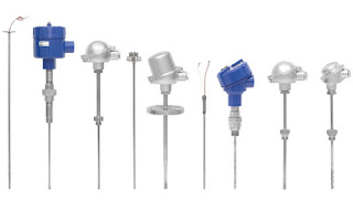
Practical Considerations for Thermocouple Selection

Industrial Thermocouples, Fixed Bend Bayonet Type
Courtesy Wika
It would be difficult to chart a career course in the industrial process control field without being exposed to thermocouples. They are the ubiquitous basic temperature measuring tools with which all process engineers and operators should be familiar. Knowing how thermocouples work, how to test them, is essential. Sooner or later, though, you may be in charge of selecting a thermocouple for a new application. With no existing part in place for you to copy, what are the selection criteria you should consider for your process?

Thermocouple sensor assemblies are available with almost countless feature combinations that empower vendors to provide a product for every application, but make specifying a complete unit for your application quite a task. Let's wade through some of the options available and see what kind of impact each may have on temperature measurement performance.

  • Thermocouple Type: Thermocouples are created using two dissimilar metals. Various metal combinations produce differing temperature ranges and accuracy. Types have standard metal combinations and are designated with capital letters, such as T, J, and K. Generally, avoid selecting a type that exhibits your anticipated measurements near the extremes for the type. Accuracy varies among thermocouple types, so make sure the accuracy of the selected type will be suitable.
  • NIST Traceability: This may be required for your application. The finished thermocouple assembly is tested and compared to a known standard. The error value between the thermocouple shipped to you and the standard are recorded  and certified. The certified sensor assembly will be specially tagged for reference to the standard.
  • Junction Type: If your sensor will be contained within a tube or sheath, the manner in which the actual sensor junction is arranged is important. The junction can be grounded to the sheath, electrically insulated from the sheath (ungrounded), or protruded from the sheath (exposed). If your process environment may subject the sensor assembly to stray voltages (EMF), it may be wise to stay away from a grounded junction, even though it provides fast response to a change in temperature. Exposed junctions provide very quick response, but are subjected to potential damage or corrosion from surrounding elements. The ungrounded junction provides protection within the enclosing sheath, with a slower response time than either of the other two junction types. When using ungrounded junctions, keep the mass and diameter of the sheath as small as might be practical to avoid overdamping the sensor response.
  • Probe Sheath Material: This applies to assemblies installed in a tube or sheath which houses and protects the sensor junction and may provide some means of mounting. Material selections include a variety of stainless steel types, polymers, and metals with coatings of corrosion resistant material to suit many applications. Make sure the sheath material, including any coatings, will withstand the anticipated temperature exposure range.
  • Probe Configuration: Sheath tube diameter and length can be customized, along with provisions for bends in the tube. Remember that as you increase the mass around the junction, or increase the distance of the junction from the point of measurement, the response time will tend to increase.
  • Wika Industrial Thermocouples, Various Termination Options
    Industrial Thermocouples, Showing Various Termination Options
    Courtesy Wika
  • Fittings and Terminations: There are innumerable possibilities for mounting fittings and wiring terminations. Give consideration to ease of access for service. How will the assembly be replaced if it fails? Are vibration, moisture, or other environmental factors a concern? What type of cable or lead wires would be best suited for the application?
Your options are so numerous, it is advisable to consult a manufacturer's sales engineer for assistance in specifying the right configuration for your application. Their product knowledge and application experience, combined with your understanding of the process requirements, will produce a positive outcome in the selection procedure.


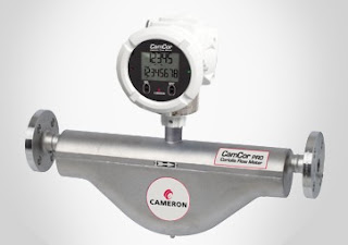
New Product From Cameron - CamCor Coriolis Flow Meters

Industrial Coriolis Flow Meter - Cameron
CamCor Pro - Industrial Coriolis Flow Meter
Courtesy Cameron
Whether it's high viscosity crude oils, ultra-low flow conditions or applications at the extremes of temperature, Cameron's new CamCor™ range of Coriolis flow meters deliver value beyond the whole-life operational benefits associated with non-mechanical architectures.

CamCor comes in two architectures, CamCor CT for custody transfer, where the emphasis particularly is on high accuracy, and the Cameron CamCor PRO for process operations.

CamCor CT offers flow rate accuracy of ± 0.1% for liquids, as a result of its deep “U” shaped dual sensors, with outstanding zero stability performance (0.071 lb/min for 2” model). The range includes models purpose-designed for application extremes, covering temperatures from -200°C (Cryogenic/ LNG) up to 350°C. Nominal sensor sizes go from less than 2mm to 250mm, with 1/4” to 10” end connections, offered in ANSI class 150 to 900, other flange types, threaded, or Tri-Clover.

The unit is manufactured of 316/316L stainless steel and Hastelloy Alloy C22.

The CamCor PRO Series possesses a flow rate turndown ration up to 50:1, flow rate accuracy of
+/- 0.2% and density accuracy of +/- 0.003 g/ml. It comes with the same transmitter, output, communications, diagnostics and configuration as the CamCor CT and is available in four nominal sensor sizes, from 6mm to 50mm, with 1/2” to 2” end connections in ANSI flanges and Tri-Clover.

Review the product brochure below, or contact a product specialist for more details or a discussion of your application.


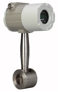
Multivariable Vortex Flowmeter

Industrial flowmeter
Multivariable Vortex Flowmeter
Courtesy Azbil North America
A new multivariable vortex flowmeter has recently been added to the product line at MS Jacobs & Associates. It is intended for industrial process measurement and control. The AX Series, from Azbil North America, utilizes a vortex shedding velocity sensor, solid state pressure transducer, and resistance temperature detector in a single unit to allow accurate measurement of mass flow in gases, liquids and steam. The combination of multiple variable measurement in a single package simplifies installation and setup cost, while reducing potential leakage paths of an arrangement employing separate instruments for each variable. The AX Series is available for in-line or insertion installation. Your product sales engineer can provide a sizing guide and other assistance in selecting and configuring the best product for your application.


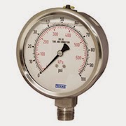
When to Use Pressure Gauge Accessories

pressure gauge
Pressure Gauge (Wika)
Gauge accessories are designed to complement a pressure gauge in order to enhance and maximize its performance. Based on the application, pressure gauge accessories may never be required; however, protecting the pressure gauge from abnormal conditions is the most common reason for choosing to use a gauge accessory. Pressure spikes, temperature fluctuations and corrosion are leading causes for premature gauge failure. Your application may benefit from a gauge accessory.

Accessories for a pressure gauge may be the extra step needed for a successful, proactive, preventative maintenance program and for extending the life of pressure gauges in environments like oil and gas, petrochemical, and chemical plants. When a pressure gauge is paired with a mini-siphon, the gauge is protected from harmful steam, vapors and liquids. When a pressure gauge is paired with an overpressure protector, the gauge is protected from pressures exceeding its maximum pressure rating. When a pressure gauge is paired with a diaphragm seal, the gauge is protected from hot, viscous, contaminated or corrosive media. When a pressure gauge is paired with a snubber, the gauge is protected from pressure pulses.

Magnetrol ECHOTEL Ultrasonic Level Switch Operating Principle

The Magnetrol ECHOTEL utilizes ultrasonic energy to detect the presence or absence of liquid in a single or dual point transducer. Ultrasonic contact level technology uses high-frequency sound waves that are easily transmitted across a transducer gap in the presence of a liquid media, but are attenuated when the gap is dry. The ECHOTEL switches use an ultrasonic frequency of 2 MHz to perform this liquid level measurement in a wide variety of process media and application conditions.

The transducer uses a pair of piezoelectric crystals that are encapsulated in epoxy at the tip of the transducer. The crystals are made of a ceramic material that vibrates at a given frequency when subjected to an applied voltage. The transmit crystal converts the applied voltage from the electronics into an ultrasonic signal. When liquid is present in the gap, the receive crystal senses the ultrasonic signal from the transmit crystal and converts it back to an electrical signal. This signal is sent to the electronics to indicate the presence of liquid in the transducer gap. When there is no liquid present, the ultrasonic signal is attenuated and is not detected by the receive crystal.


For more information on industrial level control, contact M.S. Jacobs and Associates.