Showing posts with label process measurement. Show all posts

Are You Well Grounded on Grounding? - Part 3

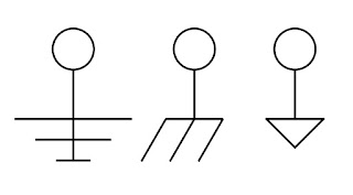
Drawing symbols for Electrical Ground
Electrical Drawing Symbols for Ground
Welcome to the third and final part of this series on electrical grounding for equipment and instruments. Part One and Part Two can be found as previous posts to this blog, and I hope you read them too. Those initial parts provided practical knowledge about equipment grounding and personnel protection in a format understandable to anyone. Those of us more deeply involved with electrical matters likely know someone that could benefit from these articles and I urge you to share.

The white paper that I have included below was produced by the folks at Acromag, a world class manufacturer of signal conditioners and other industrial I/O devices. They have done a fantastic job of presenting technical subject matter in a compact and very understandable form. The subjects covered in the series include:
  • Ground as protection
  • How a ground fault circuit interrupter (GFCI) works
  • Ground as a voltage stabilizer and transient limiter
  • Tips on improving safety and signal integrity
  • The importance of circuit grounding
  • Description of the US AC power system and its use of earth ground
This third installment includes a section entitled "Some Basic Ground Rules For Wired Equipment" which lists out an array of useful tips for connecting wired signals to devices, and more.

Product specialists are always on hand to discuss and solve your process measurement and control issues. Combine the process knowledge of the on site stakeholder with the product and application expertise of the professional sales engineer to produce the best outcomes.


Are You Well Grounded on Grounding? - Part 1

Ground Symbols
Some Drawing Symbols Used For Ground
Grounding of electrical equipment and electronic instrumentation is an aspect of project design and implementation that sometimes gets taken for granted. To say that proper electrical grounding is important is an understatement because, without it, certain safety aspects that we rely upon will simply not work. Additionally, and often more confounding, is the intermittent, unexpected, or bizarre behavior of electronic measurement and control devices when proper electrical grounding is not established.

I came across a series of white papers written by some knowledgeable people at Acromag, a manufacturer of industrial input and output devices (industrial I/O). The comprehensive three part series covers best practices involved in the grounding of electrical equipment and electronic instrumentation, in language understandable to a reader of any technical level. The subject matter includes:

  • Ground as protection
  • How a ground fault circuit interrupter (GFCI) works
  • Ground as a voltage stabilizer and transient limiter
  • Tips on improving safety and signal integrity
  • The importance of circuit grounding
  • Description of the US AC power system and its use of earth ground

In my reading of the white papers, I gathered a few things I did not know, refreshed a few I had forgotten, and reinforced my understanding of the topic. There is something in the documents for everyone, and a small investment in time will yield some benefit. All stakeholders in industrial process measurement and control, from the factory floor to the executive office, should have the basic understanding contained in these papers.

Part One of the three part series is below. Part Two and Part Three will be published simultaneously in posts following this one. You can get any level of application assistance you need from the sales engineers that specialize in industrial process equipment, measurement, and controls. Their product knowledge and technical resources, combined with your process mastery, will yield the best solution to any issue.


Big Signal Loop? Consider Using a Splitter.

Acromag Industrial Signal Isolated Transmitter
Industrial Signal Transmitters
Courtesy Acromag
Industrial process measurement and control requires the transmission of signals from point to point with no significant distortion. Even with the growing prevalence of wireless signal transmission, over-wire transmission of signals is still a primary means of connecting one device to another.
In the cabled process measurement and control world, the 4 to 20 milliampere signal is generally considered the standard for transmitting analog control and measurement signals over any distance.
There is an immense array of instrumentation and controllers available for use with 4-20 ma signals, so expertise in routing and delivering those signals should be part of your process M&C skill set.

Like just about everything else, routing 4-20 ma signals presents its own set of challenges that require some thought and planning to overcome. Electrical interference is always a concern and must be prevented from impacting the operation of measurement and control devices. Additionally, there must be sufficient power in the signal loop to accommodate the resistance load of connected devices. There are other considerations, but I'm going to focus on these two.

One scenario that can present significant issues is multiple devices requiring connection to the same signal, but with great distance between them. A simple solution can be implemented using an isolated signal splitter.

Features of these units making them an attractive, single box, solution:


  • One 4-20 ma input channel for the measuring or controlling device.
  • The input signal is retransmitted as identical isolated 4-20 ma signals
  • Galvanic isolation from input to output
  • Isolation between channels for safety and increased noise immunity. Fault in one output channel does not impact the operation of the other channels.
  • Reliable operation in industrial environments, with protection from RFI, EMI, ESD, and surges.
  • Low radiated emissions in accordance with CE requirements. 
  • DIN-rail mounting of the unit
  • Plug-in terminal blocks
If you have a very long signal loop, connecting multiple devices, consider breaking the devices into two groups that may allow for a substantially shorter cable length for each group. Connect each group to one of the isolated outputs of the splitter, giving each group of instruments the identical signal without the risks or impractically of an excessively long cable run.

There are other devices available that may combine special characteristics that solve your signal transmission challenges. Contact a product specialist and discuss your existing or anticipated project requirements. I continually urge engineers to take their process expertise, combine it with the extensive product knowledge of a professional sales engineer, and produce the best possible outcome.


Practical Considerations for Thermocouple Selection

Industrial Thermocouples, Fixed Bend Bayonet Type
Courtesy Wika
It would be difficult to chart a career course in the industrial process control field without being exposed to thermocouples. They are the ubiquitous basic temperature measuring tools with which all process engineers and operators should be familiar. Knowing how thermocouples work, how to test them, is essential. Sooner or later, though, you may be in charge of selecting a thermocouple for a new application. With no existing part in place for you to copy, what are the selection criteria you should consider for your process?

Thermocouple sensor assemblies are available with almost countless feature combinations that empower vendors to provide a product for every application, but make specifying a complete unit for your application quite a task. Let's wade through some of the options available and see what kind of impact each may have on temperature measurement performance.

  • Thermocouple Type: Thermocouples are created using two dissimilar metals. Various metal combinations produce differing temperature ranges and accuracy. Types have standard metal combinations and are designated with capital letters, such as T, J, and K. Generally, avoid selecting a type that exhibits your anticipated measurements near the extremes for the type. Accuracy varies among thermocouple types, so make sure the accuracy of the selected type will be suitable.
  • NIST Traceability: This may be required for your application. The finished thermocouple assembly is tested and compared to a known standard. The error value between the thermocouple shipped to you and the standard are recorded  and certified. The certified sensor assembly will be specially tagged for reference to the standard.
  • Junction Type: If your sensor will be contained within a tube or sheath, the manner in which the actual sensor junction is arranged is important. The junction can be grounded to the sheath, electrically insulated from the sheath (ungrounded), or protruded from the sheath (exposed). If your process environment may subject the sensor assembly to stray voltages (EMF), it may be wise to stay away from a grounded junction, even though it provides fast response to a change in temperature. Exposed junctions provide very quick response, but are subjected to potential damage or corrosion from surrounding elements. The ungrounded junction provides protection within the enclosing sheath, with a slower response time than either of the other two junction types. When using ungrounded junctions, keep the mass and diameter of the sheath as small as might be practical to avoid overdamping the sensor response.
  • Probe Sheath Material: This applies to assemblies installed in a tube or sheath which houses and protects the sensor junction and may provide some means of mounting. Material selections include a variety of stainless steel types, polymers, and metals with coatings of corrosion resistant material to suit many applications. Make sure the sheath material, including any coatings, will withstand the anticipated temperature exposure range.
  • Probe Configuration: Sheath tube diameter and length can be customized, along with provisions for bends in the tube. Remember that as you increase the mass around the junction, or increase the distance of the junction from the point of measurement, the response time will tend to increase.
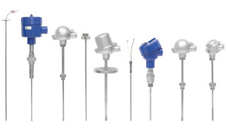
  • Wika Industrial Thermocouples, Various Termination Options
    Industrial Thermocouples, Showing Various Termination Options
    Courtesy Wika
  • Fittings and Terminations: There are innumerable possibilities for mounting fittings and wiring terminations. Give consideration to ease of access for service. How will the assembly be replaced if it fails? Are vibration, moisture, or other environmental factors a concern? What type of cable or lead wires would be best suited for the application?
Your options are so numerous, it is advisable to consult a manufacturer's sales engineer for assistance in specifying the right configuration for your application. Their product knowledge and application experience, combined with your understanding of the process requirements, will produce a positive outcome in the selection procedure.


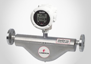
New Product From Cameron - CamCor Coriolis Flow Meters

Industrial Coriolis Flow Meter - Cameron
CamCor Pro - Industrial Coriolis Flow Meter
Courtesy Cameron
Whether it's high viscosity crude oils, ultra-low flow conditions or applications at the extremes of temperature, Cameron's new CamCor™ range of Coriolis flow meters deliver value beyond the whole-life operational benefits associated with non-mechanical architectures.

CamCor comes in two architectures, CamCor CT for custody transfer, where the emphasis particularly is on high accuracy, and the Cameron CamCor PRO for process operations.

CamCor CT offers flow rate accuracy of ± 0.1% for liquids, as a result of its deep “U” shaped dual sensors, with outstanding zero stability performance (0.071 lb/min for 2” model). The range includes models purpose-designed for application extremes, covering temperatures from -200°C (Cryogenic/ LNG) up to 350°C. Nominal sensor sizes go from less than 2mm to 250mm, with 1/4” to 10” end connections, offered in ANSI class 150 to 900, other flange types, threaded, or Tri-Clover.

The unit is manufactured of 316/316L stainless steel and Hastelloy Alloy C22.

The CamCor PRO Series possesses a flow rate turndown ration up to 50:1, flow rate accuracy of
+/- 0.2% and density accuracy of +/- 0.003 g/ml. It comes with the same transmitter, output, communications, diagnostics and configuration as the CamCor CT and is available in four nominal sensor sizes, from 6mm to 50mm, with 1/2” to 2” end connections in ANSI flanges and Tri-Clover.

Review the product brochure below, or contact a product specialist for more details or a discussion of your application.


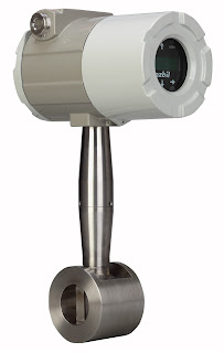
Multivariable Vortex Flowmeter

Industrial flowmeter
Multivariable Vortex Flowmeter
Courtesy Azbil North America
A new multivariable vortex flowmeter has recently been added to the product line at MS Jacobs & Associates. It is intended for industrial process measurement and control. The AX Series, from Azbil North America, utilizes a vortex shedding velocity sensor, solid state pressure transducer, and resistance temperature detector in a single unit to allow accurate measurement of mass flow in gases, liquids and steam. The combination of multiple variable measurement in a single package simplifies installation and setup cost, while reducing potential leakage paths of an arrangement employing separate instruments for each variable. The AX Series is available for in-line or insertion installation. Your product sales engineer can provide a sizing guide and other assistance in selecting and configuring the best product for your application.