Flexible Hazardous Gas Detection Monitoring System

Hazardous gas detection monitoring unit
Sentry IT Controller For Hazardous Gas Detection Monitoring
Courtesy Sierra Monitor
Industrial processes, by their scale and nature, are rife with hazards. As a process designer, engineer, or operator, protection of the facility, employees, and surrounding community ranks highest among our many responsibilities. Some hazards are apparent, visible, easily detected. Others are not. Technology and ingenuity play a substantial role in providing acceptable levels of safety in modern facilities.

Properly designing a hazardous gas monitoring system starts with identifying the target elements and their sources. Gaseous hazards can generally be divided into three general classes, all of which can be specifically targeted with a properly configured gas monitoring system.


  • Combustible gas concentrations subject to ignition and explosion.
  • Toxic gas with inherent personnel risk.
  • Insufficient oxygen levels to support human respiration.

The best overall system configuration can be achieved through a combination of detectors, communications, and response that will provide accurate sensing of the target hazard, reliable and predictable transmission of information, and preconfigured response when alarm limits are triggered. Some product features for the detector monitor that may prove useful in a well specified installation:

  • A means to non-intrusively calibrate all sensors at the same time
  • Ability to diagnostically monitor connected sensors for performance.
  • Provision of an easily operable interface for users.
  • Battery backup to maintain operation during a power outage.
  • Network and protocol compatibility with a range of industry accepted standards.
  • Simple means to upgrade operating software.
  • Compatibility with detection devices from a broad array of sources.
  • Input capacity for more sensors than your current requirement.
I have included a bulletin describing such a unit, manufactured by Sierra Monitor. Browse the document and contact a hazardous gas detection application specialist to get more details and discuss your hazardous gas detection challenges. The best solutions come from combining your process knowledge and experience with that of a product application specialist.


Industrial I/O Applications Compilation Provides Answers

Process Measurement and Control Input and Output Devices
Process Measurement and Control I/O Devices
Courtesy Acromag
Process measurement always presents two basic challenges, derive a measured value of the process condition, then transmit or deliver that value to a recording or decision making device. Your knowledge and ingenuity applied to the design and implementation of these measurement and transmission functions are the key to how effectively your control system will function. Acromag, a world class manufacturer of signal conditioning equipment and industrial I/O devices, has produced a compilation of applications that illustrate some creative and best practices for establishing effective connections between control and measurement devices. The applications are drawn from defense, power generation, and manufacturing, but the knowledge shared can be broadly applied to many industries.

Look through the applications and you will find something of value. You can always contact a product and application specialist to discuss your process measurement and control challenges and requirements. Combining their product application expertise with your process knowledge will generate the best solutions.


Rotameters For Flow Measurement - Selecting the Right One

Industrial rotameter flow meters
Industrial Rotameter Flow Meters
Courtesy King Instrument
Applied extensively in industrial process measurement and control, a rotameter is an instrument that uses a float of given density to establish, for any measurable flow rate, an equilibrium position within the fluid stream where the force of the flowing fluid equals the force of gravity. Let's break that down a little. A rotameter has a tapered tube with a float inside. As the measured fluid flows upward through the tube, it pushes the float upward along the length of the tube. As the float rises in the tube, the cross sectional area of the tube increases and more fluid can bypass around the float. At some point, the upward force of the fluid flow acting on the float will balance with the downward force of gravity. The position of the float along the length of the tube correlates with a certain flow rate when certain properties of the fluid are known. Flow rate scale graduations on the tube can be read by the operator.

Rotameters are very specific to each flow measurement application. It's important that you know your fluid properties, ambient conditions, connection and readability specifications. 

Start with these selection parameters:

  • Desired flow rate range
  • Fluid specific gravity
  • Ambient temperature
  • Operating and maximum pressure
  • Line size
  • Connection type
  • Connection orientation
  • With or without a valve
  • Material requirements to accommodate fluid
  • Scale units of measure. Smallest scale divisions needed.
For each application, it's advisable to work closely with a sales engineer to gather all the needed information and coordinate the product selection process.

Here are some things to consider for potential rotameter applications:


  • Simple design and operation provide a modest cost solution.
  • No external power is required for operation. Inherent fluid properties and gravity are used to measure flow rate.
  • Clear glass used for the measuring tube is highly resistant to thermal shock and corrosion.
  • Instrument orientation must be vertical, with fluid flowing upward.
  • Scale graduations are accurate for a given substance at a given temperature, making the devices application specific.
  • Operation of the rotameter may be impacted by changes in the viscosity of the fluid. Consult with a product and application specialist to explore your application.
  • Direct flow indication provides resolution that may not be as good as some other flow measurement methods.
  • Visual reading of the scale is subject to uncertainty due to float oscillation, parallax, and location on the scale.
  • Make sure the fluid turbidity, or another fluid characteristic will not obscure the visibility of the float.

Consult with a product specialist about your flow measurement application. A combination of your process knowledge and their product expertise will produce the best solution.


Analynk Wireless Updated Website

Analynk Wireless company logo
Analynk Wireless has a new website
One of the manufacturers represented by MS Jacobs & Associates, Analynk Wireless, has redesigned and published an updated website. The new site provides access to features, model configurations and datasheets for their entire range of industrial process control and measurement products. Analynk's product line complements those of other manufacturers in the MS Jacobs portfolio of industrial instrumentation and process control products. MSJ employs the Analynk products, often in combination with products of their other manufacturer lines, to provide complete packaged process control solutions for their customers.

Analynk Wireless encompasses three groups of products:

  • Hazalynk® wireless products for hazardous areas, including explosion proof antennas and hazardous area access point enclosures.
  • Sensalynk® single and multi-point wireless transmitters, receivers, and repeaters for industrial wireless networking.
  • Telmar® transmitters, tachometers, signal alarms, power supplies, indicators and meters for process measurement and control.
Take a look at the new Analynk website. Discuss your process improvement ideas with product application specialists and develop a plan to generate better outcomes.

Application Suitability of Ultrasonic Flowmeters

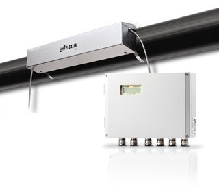
Ultrasonic Liquid Flow Meter
Ultrasonic Liquid Flow Measurement System
Courtesy Flexim America
Industrial process control frequently requires the accurate measurement of fluid flow. There are several widely applied methods for measuring flow, each having particular advantages which may apply to a specific application.

Ultrasonic flow meters measure flow indirectly by calculating transit time of a sound wave through, or reflecting from, a flowing fluid. The velocity of the fluid has an impact on the transit time, from which a flow rate can be calculated. Attributes of ultrasonic flow measurement that may determine suitability for a particular application include:

  • Transducers can be clamped on exterior pipe surface where measurement is needed.
  • Non intrusive measurement technology prevents contact between media and measuring elements.
  • No significant pressure drop associated with measuring device installation.
  • Reduced leak potential.
  • No moving parts.
  • Comparatively higher cost than some other technologies.
  • Fluid characteristics must be well known for proper application.
  • Pipe cross section must be completely filled by media to acquire accurate flow measurement.
Learn more about this process measurement and control technology in the product detail sheet below. Consult with a product application specialist for more detailed product information and tips on how to best apply ultrasonic flow meters to your process.


Avoid Process Downtime With Five Device Protection Considerations

Industrial Process Instruments
Industrial process control is everywhere. Sometimes it is dangerous or complex. In other cases it may be relatively mundane. In all industrial processes, though, maintaining operation is key. Stakeholders rely on the process output and look to the designers, engineers, and operators to deliver, in many cases, uninterrupted performance. The world is a place of many uncertainties, some of which can impact your process in undesirable ways. While it's not practical to design or build to accommodate every possible adverse event, application of experience and good judgement in a few areas may significantly shorten the list of things that can negatively impact your process.

Process control is achieved through the measurement of various conditions and application of regulated adjustments to the process inputs to deliver a desired output. Process variable measurement serves as the input to the control system. In the industrial sphere, it is common to see devices used for the measurement and transmission of temperature, pressure, flow, mass, level, and electrical parameters like voltage, current, capacitance and more. Regardless of what is being measured, there are three common characteristics:

  • Device - A combination of a sensor and a translator that together detect some physical condition of the process and produce an output signal that can be correlated to the process condition. 
  • Location - The device will have a location that is dictated by the process construction and arrangement. Device locations have a tendency to be inflexible.
  • Signal transmission path - Unless the control element is integral to, or adjacent to, the measurement device, there will be some path over which the measurement signal must travel to reach an associated control element. 

Looking at these three elements for each measurement point, consider the five risk categories below in evaluating what you can do to safeguard your process measurement instrumentation. It's advisable to open a conversation with an experienced application specialist and freely discuss your concerns. Gathering additional input from various experienced sources will help you determine how extensive your protective measures should be to deliver a balance between cost and the probability of certain adverse events.

  • Local Weather: There is local weather data available for almost every place on the planet. Take the time to procure reliable data and examine the distribution of temperature, humidity, precipitation, and wind conditions throughout all seasons. Clearly, if portions of the process are located outdoors, extreme local weather conditions will need to be accommodated. Even if your process is located indoors, local weather information is important if the process is to operate continuously. Consider whether an indoor process must continue to operate, even if the building HVAC system fails and indoor conditions begin to be impacted by outdoor conditions. Also, depending upon the design of the building climate control system, changing outdoor conditions can have a noticeable and possibly significant impact on the indoor air conditions.
  • Process Generated Conditions: There may be specific aspects of your process that produce occurrences of vibration, pressure spike, electrical interference, or a host of other aberrations that may affect the proper operation of measurement devices. Know your process....really know it. Protect instrument sensors from potentially damaging transients and other process conditions that can be reasonably expected to occur. Device location relative to sources of electrical interference, elevated temperature, vibration, shock, and other transient conditions should be considered.
  • Security: Your design goal should be to achieve a very high level of certainty that the signals generated by the measurement devices are uninterrupted and reflect the actual process conditions. There are two cases I always consider for security. The first is cyber, which applies in the case of a process measurement device network connection. Necessary steps should be taken to thwart an attempt to breach the network and detect unusual conditions that might indicate an invader's attempt to manipulate the process. My second case is related to device access by those without proper knowledge, training, or permission. Protection from these threats will likely involve a combination of physical barriers and procedures.
  • Physical Contact: Industrial settings are, well, industrial. Large, heavy, irregular, unwieldy, and sharp things can sometimes be moved through areas occupied by process measurement gear. Technicians with carts, tools, and materials frequently pass through process areas to do their work. Protecting equipment and instruments from damaging contact pays dividends for the life of the installation. Consider, in your design and layout, the proximity of instruments to areas of traffic. If applicable, also consider areas overhead. The level of protection will need to be balanced with the need for access by qualified individuals for service, maintenance, calibration, and observation, as applicable.
  • Moisture: Electronics are a mainstay of modern measurement instrumentation. Clearly, liquid moisture must be kept from contact with electronic circuits. Vaporous moisture will find a path to the internals of your electronic devices. This vapor, which is present in considerable levels in almost every indoor and outdoor environment, can condense when the right conditions are present. It is imperative that enclosures, conduit, boxes, fittings must be provided with barriers to moisture entry and/or a reliable means to automatically discharge accumulated liquid moisture before damage occurs.
There is much to think about in the realm of device protection. Balancing the costs of protection, the impact of protective measures on the ability to service and operate the process, and the risk involved with process failure or shutdown requires the application of technical expertise, experience, and sound practical judgement. Draw information and opinion from multiple sources, including sales engineers. Combine their product application knowledge with your process expertise to make good decisions.


Application Advantages of Intrinsically Safe Barriers

2-Wire Transmitter in Hazardous Area With Intrinsic Safety Barrier
Courtesy Ronan Engineering Company

Industrial process measurement and control operations have few boundaries. Land, sea, air, light, dark, dry, wet, hot, cold, indoor, and outdoor environments. Did I mention potentially explosive? Well, there is that, too.

If your experience was anything like mine, it is likely that your first project involving a hazardous area really drove home the fact that you are working at a very serious endeavor. In addition to quality problems or downtime resulting from equipment failure, now you add "the place blows up" to the list of possible outcomes. It's sobering, and not the type of situation where you have the option of real world testing. You need to be right the first time. Every remotely possible source of ignition must be considered and rendered harmless.

One way to provide the necessary level of safety is through the use of explosion proof enclosures, conduit, fittings, and other devices. By their nature, these items are designed to contain an internal explosion and provide for the expansion and cooling of the ignited gases into the surrounding atmosphere. The expansion cools the hot gas to a temperature safe for venting from the enclosure into the hazardous area without causing an ignition.

There is a good solution for measurement and control circuits requiring only low power levels. Intrinsically safe circuit designs employ barriers that allow power limited connections between devices in a hazardous zone and those in a non-hazardous zone. Intrinsic safety relies on the limiting of available energy in the system to a level that will not ignite a hazardous atmosphere (explosive gas or dust). Without significant energy storage, and ensuring that only low voltages and currents enter the hazardous area, intrinsically safe design removes the circuit as a possible ignition source. Where it is possible to utilize an intrinsically safe circuit, there are some advantages over using an explosion proof design.

  • Absence of explosion proof enclosures enhances the accessibility of system components.
  • Personnel safety is increased with low voltage operation.
  • Standard wiring methods and materials may be used. No explosion proof conduit, boxes, fittings.
  • Calibration and maintenance can be performed with the system in operation.
  • Special skill levels required by an explosion proof design are not required with intrinsically safe design.
A primary device in an intrinsically safe circuit will be the barrier. The intrinsic safety barrier forms the border between the hazardous and non-hazardous areas. There are other design considerations, all of which you should discuss with knowledgeable application specialists. I have included a document below from Ronan Engineering Company, a manufacturer of intrinsic safety barriers. It provides some additional useful information, including a listing of the many I/O applications where the barriers can be employed.