Thermal Flow Meters

Thermal flow meter for industrial process measurement
Magnetrol TA2 thermal flow meter configured
for insertion mounting.
Image courtesy Magnetrol International 
There are numerous methods and technologies adapted for the measurement of fluid flow, each with its own set of positive attributes and limitations. Understanding the basic operating principles behind each is useful for effective selection of a technology to be applied on a specific application. One technology long employed for continuous fluid flow measurement is thermal dispersion. The operation of a thermal flow meter is as simple as placing a heated object into a moving stream. The amount of heat drawn away, or dispersed, from the heated object is a measurable quantity that is directly proportional to mass flow rate. This is similar in concept to a principle commonly observed in wind chill where someone perceives the temperature to be colder than it actually is at the moment of measurement.

One example of a thermal mass flow meter is a hot wire anemometer, with which air speed is measured via a metal wire charged with an electric current. The faster the air moves around the wire, the more the temperature of the wire will correspondingly drop. The electrical power required to keep the temperature of the wire constant is directly proportional to the flow rate of the air moving past the wire. However, thermal flow meters are inherently used to measure mass air flow and not volumetric air flow.

A common application of thermal flow meters is mass air flow measurement for combustion control, such as in engines and boilers. Maintaining fuel to air ratios in a range resulting in efficient combustion is essential to controlling fuel costs and the level of regulated emissions. Keeping combustion efficient relies on a controller’s ability to modify the combustion air mass flow rate to match the demand for fuel under changing load and input conditions. Thermal dispersion technology can be applied to gases or liquids, making the range of applications very broad.

Typically, thermal mass flow meters used in processing industries will have a flow tube or insertion probe with two temperature sensors, one which is heated and the other which is not. The heated sensor serves as the mass flow sensor, meaning it will cool at a rate directly dependent on mass flow. The purpose of the second temperature sensor is to deliver an accurate measure of fluid temperature. Various processing methods are employed to determine the degree of thermal dispersion, but all are related to the same basic principal.

One of the best applications for thermal mass flow meters is at a particular point of a flow stream, where the flow meter can be inserted or installed to measure a specific amount of fluid being used in the process, such as the amount of gas being sent to a flare. Their design simplicity and ease of production allows thermal flow meters to be very compact. Some are even coupled with built-in throttling mechanisms and other control devices, incorporating measurement and control functions into a single integrated device.

Share your flow measurement requirements and challenges with an instrumentation specialist, combining your own process knowledge and experience with their product application expertise to develop an effective solution.

Motion Detection For Materials Conveying Equipment

Instrument for detecting loss of motion in material conveying system
Loss of motion detector for use in material
conveying systems
Image courtesy Ronan Engineering
Processing equipment in many facilities involves moving materials along a conveyance system from one point to another. Continuous processing requires that the conveyance machinery keeps moving materials through the process. Monitoring movement at selected points along the conveyance can provide immediate notification when machine motion stops.

One motion monitoring unit from Ronan Engineering has been in the market for many years, evidence of its durability and reliability for detecting loss of motion. The X25 has a very simple operating principle. A detector head is located adjacent to a rotating shaft, spoke wheel, screw conveyor, bucket elevator, or other moving part of the equipment. It functions as a pickup with an output signal corresponding to movement of the target. A remotely located housing contains the signal processor with adjustable sensitivity and time interval controls, as well as output relays for signaling loss of movement in the targeted area.

There are a number of adaptations that can be made for installations subject to low rotational speed, high temperature, and other special conditions. The device is simple, rugged, and reliable.

More detail is provided in the data sheet included below. Share your potential applications with process measurement and control specialists. Leverage your own knowledge and experience with their product application expertise to develop an effective solution.


Automatic Self Cleaning Strainer for Fluid Processing

cutaway view of automatic self cleaning strainer
An automatic self-cleaning strainer is suitable for many
applications and reduces manual maintenance.
Strainers and other filtration equipment reduce the burden of targeted unwanted solids in a fluid system. Potentially damaging particulate material is trapped and held for removal from the system. Keeping fluid systems clean helps to maintain long term design performance and potentially extends the operating life of pumps, valves, and other mechanical devices in the system.

Strainers generally consist of a heavy duty housing and a contained screen with controlled opening size designed to disallow the passage of particles exceeding a targeted size. Trapped particulates remain on the screen, or within a shape created by the screen such as a basket (see basket strainer). The continuing collection of solids will eventually impede the free flow of the process fluid, so the strainer must be emptied or cleaned periodically. The frequency of cleaning is a function of the solids content of the incoming fluid and may not necessarily be a regular interval. A simple strainer, to be cleaned, requires temporary shutdown of the flow or bypass of process fluid around the strainer assembly. A duplex strainer consists of twin strainers, usually housed in a common assembly, with a diverter valve that allows the inlet flow to be directed to one of the strainers while closing off the other from the system. This allows for cleaning of one of the strainers while the other is in active service, maintaining continuous fluid flow.
A third solution provides the continuous operation of a duplex strainer, but without the need for manual cleaning. 
An automatic self-cleaning strainer, such as the MCS 500 from Eaton provides uninterrupted operation without a duplex configuration or regular manual cleaning. It's form is essentially a housed strainer with a built-in scraper blade that moves along the inlet surface of the strainer media, moving accumulated solids to a collection chamber at the bottom of the pressure housing. Automatic controls regulate the operation of the scraper and discharge valve on the purge chamber that removes the collected solids from the system. The automatic self-cleaning strainer provides a cost effective time saving solution for the filtration of compatible fluids.

More detail for the MCS 500 is provided below. Share your fluid filtration requirements and challenges with fluid processing specialists. Leverage your own process knowledge and experience with their product application expertise to develop effective solutions.


A Little History

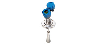
26 GHz radar level measurement transmitter
Pulsar® R86 Radar Level Transmitter
One of Magnetrol's recent innovations.
Some companies, through hard work, innovation, and good fortune, manage to stand the test of time and thrive for decades in a competitive environment. The manufacture of process measurement and control equipment and devices is an arena where standing still in the market is not a viable business strategy. Magnetrol has been helping process operators measure and control fluid level and flow for decades. The company recently posted an article on their own blog outlining a little of the company history as illustrated through product innovations. We include an excerpt from the blog below and encourage readers to share their fluid level and flow challenges with application specialists. Leveraging your own process knowledge and experience with their product application expertise to develop effective solutions.

This year marks the 85th anniversary of the founding of Magnetrol®. Since its very beginning, MAGNETROL has been a company focused on level and flow measurement innovation, designing cost-effective, cutting-edge solutions for its customers. In honor of 85 years of success, here’s a look back on some MAGNETROL highlights over the years. 
The Beginning
The history of MAGNETROL dates to 1932 as a Chicago-based manufacturer of boiler systems. The first MAGNETROL level control was born when the founding company, Schaub Systems Service, needed a controller for its boiler systems. Our innovative device was the first of its kind to accurately and safely detect the motion of liquid in boilers and feedwater systems. Soon the MAGNETROL name became synonymous with rock-solid, reliable mechanical buoyancy controls.

Mechanical buoyancy isn’t the only area where MAGNETROL has been a force for innovation. Our devices have changed the radar landscape as well. In 1998, we introduced the Eclipse® Model 705 as the first loop-powered guided wave radar (GWR) transmitter for industrial liquid level applications. The unprecedented reliability and accuracy of the ECLIPSE 705 set a new standard for radar devices.Innovation in Radar
We didn’t stop there, continuing to develop radar technology and adapt it to the needs of our customers. In 1999, MAGNETROL released the first ECLIPSE high-temperature/high-pressure probe, rated to 750 °F (400 °C). We developed an overfill-capable coaxial probe in 2000. And in 2001, we became the first company to incorporate GWR technology into a patented magnetic level indicator chamber, offering true redundant measurement.
In addition to these new developments in GWR, MAGNETROL created many pulse burst and non-contact radar devices for use in challenging process applications. We also secured our core capabilities in electronic technologies, including RF capacitance and ultrasonic.
 Looking Toward the Future
Most recently, MAGNETROL released the Pulsar® Model R86, a groundbreaking new 26GHz non-contact radar featuring a smaller wavelength for smaller antennas and improved 1mm resolution.
We continue to raise the bar for level and flow measurement. Whatever the future of industrial technology, MAGNETROL will be in the thick of it, developing the products that bring customers accuracy, reliability and peace of mind. We are a team of innovators—and innovators are always moving forward.