Showing posts with label Western New York. Show all posts

Hybrid Solar TEG Power Systems

hybrid solar PV photovoltaic thermoelectric generator TEG power system
Hybrid system shown in remote installation
Courtesy Gentherm Global Power Technologies
There are remotely located instruments and equipment throughout the world in places without available grid power. A suitable and reliable means to provide electric power is required as a standalone system for each of these instances. Photovoltaics is an obvious choice for power source, but there is another option that may provide substantial benefit for many installations.

A hybrid solar TEG (thermoelectric generator) can overcome some of the shortcomings of a pure PV system by delivering battery charging current during conditions when solar generated power is insufficient. The TEG uses heat from burning fuel to produce electric power, and can deliver charging current when the PV portion of the system fails to provide sufficient output.

  • Extended periods of bad weather. While this scenario can be compensated for with a larger battery array, there is still a limit to the performance period. Larger battery banks increase unit cost, size and weight.
  • Extreme low temperature. Battery capacity decreases during cold weather, requiring a larger battery array to provide design power output and reserve.
  • Low solar exposure during certain times of the year, requiring more solar panels to accomodate the system power requirements during times of reduced sunlight. This increases unit size and capital cost.

Critical power systems must be designed to deliver sufficient power under all environmental conditions that can be experienced at the installation site. This drives pure PV system designers to substantially oversize panel and battery arrays to assure power delivery throughout an entire year. A hybrid solar TEG system does not need to have the enormous headroom built into the design that a pure PV does. The TEG can produce power at a known rate, regardless of the surrounding environmental conditions. The potential benefits from the hybrid power system include: 

  • Reduction in solar panel array size and cost
  • Lower battery count, with reduction in capital cost, replacement cost, unit size and weight
  • Longer battery life
  • Less on-site fuel vs. a conventional fuel-based system
  • No more than once-per-year maintenance visits
  • Increased reliability over a pure PV installation

Share your remote installation power requirements and challenges with a product application specialist and bring the benefits of a hybrid solar TEG power system to your operation.


Switching Inductive Loads With Relays and Solid State Devices in Process Control

control panel interior process automation and control panel
Switching devices must be properly protected for longevity
We connect a lot of black boxes together in our control systems, not really knowing what goes on inside. There is a basic understanding of function, but maybe not enough knowledge to thoroughly assess all aspects of integrating a device into a train of control system components. We range from novice to seasoned expert, so Acromag, manufacturer and global supplier of I/O devices for process control, has provided a useful application note regarding the protection of devices employed to switch inductive loads.

The application paper provides a good explanation of what an inductive load is, and how it can impact the performance and longevity of a switching device. The document further explains how to offset the potentially damaging impact of an inductive load on a connected switching device, with specific examples and recommendations on how to put the protective measures in place. It is useful information.

The paper is provided below. Share your I/O and other process measurement and control challenges with application specialists, combining your own process knowledge with their product application expertise to develop effective solutions.


Selecting the Right Temperature, Pressure, or Differential Pressure Switch

industrial temperature switch pressure switch differential pressure switch
Temperature, pressure, and differential pressure switches come in a wide variety of configurations
Courtesy Ashcroft
Industrial process control applications present dynamic and varied requirements for measuring, monitoring and control. Each point calls for specific evaluation of the information needed from the process point for use in monitoring process performance, or control to be applied at the process point to regulate an outcome. Sometimes, a continuous analog signal is needed to provide indication across a range of values. Other times, it is only necessary to have notification of, or take action when, a certain temperature or pressure related event occurs. In those cases, a simple and reliable device can adequately meet the project requirements.

Temperature, pressure, and differential pressure switches connect to a process and change their switch position when a setpoint condition is reached. The are simple to understand, easy to install, low in cost, and require little maintenance of attention. The switches are available in an extensive array of configurations, with options to fill out almost any application requirement.

Ashcroft, global supplier of temperature and pressure switches, has produced a simplified guide that enables a designer or specifier to quickly focus their search on the right product. It is provided below for your use. Alternately, you can always share your process measurement and control requirements and challenges with product application specialists, combining your own process knowledge with their product expertise to develop effective solutions.


CSB Case Study of Industrial Plant Heat Exchanger Explosion

heat exchangers at industrial plant
Two heat exchangers at chemical plant
Industrial accidents, whether minor or catastrophic, can serve as sources of learning when analyzed and studied. Operators, owners, and technicians involved with industrial chemical operations have a degree of moral, ethical, and legal responsibility to conduct work in a reasonably and predictably safe manner without endangering personnel, property, or the environment. Part of a diligent safety culture should include reviewing industrial accidents at other facilities. There is much to learn from these unfortunate events, even when they happen in an industry that may seem somewhat removed from our own.

The U.S. Chemical Safety Board, or CSB, is an independent federal agency that investigates industrial chemical accidents. Below, find one of their video reenactments and analysis of an explosion that occurred at a Louisiana chemical processing plant in 2013. A portion of the reenactment shows how a few seemingly innocuous oversights can combine with other unrecognized conditions that result in a major conflagration.

Check out the video and sharpen your sense of awareness for potential trouble spots in your own operation.

Improved Level Measurement Contributes to Reduced Heat Rate in Steam Production

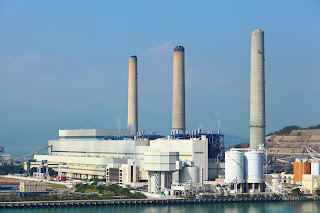
Power plant electrical generating plant
Minimizing heat rate and emissions for steam plants
Steam production is a costly operation in any facility, but is of paramount importance in power generation plants. The bottom line of a combustion based power generation facility is sensitive to the cost of input fuel. Measures that can be taken to reduce fuel input for a unit of power output (called heat rate) can translate directly into profitability. An additional benefit of reducing heat rate is a commensurate reduction in emissions.

A major contributor to heat rate reduction is the recovery of heat from the process and transference of that heat into the boiler feedwater. A sizable feedwater preheater of the shell and tube type is used to recover the heat. Shell and tube heat exchanger efficiency can be maximized with accurate control of liquid level.

Magnetrol, globally recognized leader in level measurement technology, makes the case for using guided wave radar level measurement technology as the most advantageous means for this application. The video below describes the process and how the guided wave radar level transmitter can provide the best performance.

Magnetrol has an information kit devoted to heat rate reduction. Share your steam system and level measurement challenges with a product specialist, and ask how you can get the Heat Rate Reduction Kit. Combining your facility and process knowledge with the product application expertise of a specialist will result in effective solutions.

Basics of Infrared Flame Detection

flame detector
Triple IR flame detector
(courtesy if Sierra Monitor)
A flame detector is a specialized sensor used to detect and respond to the presence of a flame, and accordingly notify an operator, sound an alarm, close a fuel supply valve, shut down a pump, and turn on a fire suppression system. 

Flame detectors are fast acting and accurate, much more so than smoke or heat detectors because of the technology they employ. Some flame detectors can detect fires up to 215 feet away and be accurate enough to detect a 1 sq. foot gasoline pan at 215 feet in less than 5 seconds. 

One popular type of flame detection technology used is measuring infrared (IR) light coming from a source. This type of sensor monitors the infrared light spectrum for very specific patterns given off by hot gases. These hot gases are sensed by a specialized fire-fighting thermal imaging (thermographic) camera. 

One method of determining if a fire exists is by looking for the infrared peak of hot carbon dioxide (approximately 4.4 micrometers). Response times of a typical IR detector is 3–5 seconds. 

There is the possibility, however, of false alarms caused by background thermal radiation and other hot surfaces in the area. Another potential concern is with the formation of condensate on the flame detector's lens, which can greatly reduce its accuracy. Direct exposure to sunlight for these types of detectors can also be problematic. 

An approach to overcome these issues is with dual or triple IR sensors, which compare the threshold signal in two or three infrared ranges. Often one sensor looks at the 4.4 micrometer carbon dioxide (CO2) emission, while the other sensors looks at additional reference frequencies. Modern flame detector design allow users to select different sensitivity levels to ensure no other detectors cross-over detection zones. 

Additional important features to be considered are heated windows to eliminate condensation and icing, HART and Modbus capabilities for digital communications, low excitation power, and compact design. 

When selecting a flame detector for any application, it is important to make sure it is approved and certified for that specific use. Check for third party agency approval including FM, ATEX, IECEx, TUV, and CSA. These approvals and certifications assure the highest quality of products and performance.

Finally, the proper application of flame detectors is critical in many applications for the safety and protection of property and personnel. Therefore, it is always suggested that your application be discussed with a qualified application engineer

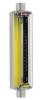
Steps to Installing a Rotameter

Rotameter
Rotameter


A rotameter, also known as a variable area flowmeter, is a device that measures the flow rate of liquid or gas in a closed tube. It measures flow rate by allowing the cross-sectional area the fluid travels through, to vary, causing a measurable effect. They are a cost-effective flow measuring device that provides excellent repeatability, requires no external power, can be made from a wide variety of materials, and may be designed for high pressure and high temperature applications.

The following are helpful, general guidelines in the proper installation of rotameters:
  1. Inspect meter for damage that may have occurred during shipping. Report any damage to the container to the freight carrier immediately. 
  2. Make sure your pressure, temperature, fluid and other requirements are compatible with the meter and components (including o-rings). 
  3. Select a suitable location for installation to prevent excess stress on the meter which may result from: 
    • Misaligned pipe. 
    • The weight of related plumbing. 
    • “Water Hammer” which is most likely to occur when flow is suddenly stopped as with quick closing solenoid operated valves. (If necessary, a surge chamber should be installed. This will also be useful in pressure start-up situations.) 
    • Thermal expansion of liquid in a stagnated or valve isolated system. 
    • Instantaneous pressurization which will stress the meter and could result in tube failure. note: In closed thermal transfer or cooling systems, install the meter in the cool side of the line to minimize meter expansion and contraction and possible fluid leaks at the threaded connections. 
  4. Handle the meter carefully during installation. 
    • Use an appropriate amount of teflon tape on external pipe threads before making connections. Do not use paste or stick type thread sealing products. 
    • Over tightening of plastic connections may result in fitting damage. 
  5. Install the meter vertically with the inlet port at the bottom. 
  6. Meters with stainless steel fittings will support several feet of pipe as long as significant vibration or stress resulting from misaligned pipe are not factors. 
  7. Meters with plastic fittings must be installed so that fittings are not made to support any part of the associated plumbing. In addition, meter frame should be fastened to bulkhead, panel or column. 
  8. Meters used in gas service should have suitable valves plumbed in at the inlet and outlet of the meter. These valves should be no more than 1-1/2 pipe diameters from the meter ports. The valve at the outlet should be used to create back pressure as required to prevent float bounce. It should be set initially and then left alone. The inlet valve should be used for throttling purposes. Depending on the installation, valves may not be essential, but they are most useful in many installations. Remember: To get a correct reading of flow in gas service, it is necessary to know the pressure right at the outlet of the meter (before the valve). 
  9. Pressure and temperature maximums must never be exceeded

Measuring Flow - The Transit-Time Difference Method

transit-time difference method
Transit-time difference Method
(courtesy of FLEXIM)

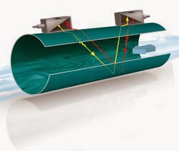
The Transit-Time Difference method exploits the fact that the transmission speed of an ultrasonic signal depends on the flow velocity of the carrier medium.

Similar to a swimmer swimming against the current, an ultrasonic signal moves slower against the flow direction of the medium than when in flow direction.

The Measurement Principle

transit-time difference method
Diagram of FLEXIM transit-time
difference flow meter design.
For the measurement, two ultrasonic pulses are sent through the medium, one in the flow direction, and a second one against it. The transducers are alternatively working as an emitter and a receiver.

The transit-time of the ultrasonic signal propagating in the flow direction is shorter than the transit-time of the signal propagating against the flow direction. A transit-time difference, Δt, can thus be measured and allows the determination of the average flow velocity based on the propagation path of the ultrasonic signals.

An additional profile correction is performed by proprietary FLEXIM algorithms, to obtain an exceptional accuracy on the average flow velocity on the cross-section of the pipe - which is proportional to the volume flow.

Since ultrasounds propagate in solids, the transducers can be mounted onto the pipe.

The measurement is therefore non-intrusive, and thus no cutting or welding of pipes is required for the installation of the transducers.


When to Use Pressure Gauge Accessories

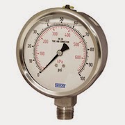
pressure gauge
Pressure Gauge (Wika)
Gauge accessories are designed to complement a pressure gauge in order to enhance and maximize its performance. Based on the application, pressure gauge accessories may never be required; however, protecting the pressure gauge from abnormal conditions is the most common reason for choosing to use a gauge accessory. Pressure spikes, temperature fluctuations and corrosion are leading causes for premature gauge failure. Your application may benefit from a gauge accessory.

Accessories for a pressure gauge may be the extra step needed for a successful, proactive, preventative maintenance program and for extending the life of pressure gauges in environments like oil and gas, petrochemical, and chemical plants. When a pressure gauge is paired with a mini-siphon, the gauge is protected from harmful steam, vapors and liquids. When a pressure gauge is paired with an overpressure protector, the gauge is protected from pressures exceeding its maximum pressure rating. When a pressure gauge is paired with a diaphragm seal, the gauge is protected from hot, viscous, contaminated or corrosive media. When a pressure gauge is paired with a snubber, the gauge is protected from pressure pulses.