Showing posts with label west virginia. Show all posts

Steps to Installing a Rotameter

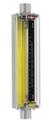
Rotameter
Rotameter


A rotameter, also known as a variable area flowmeter, is a device that measures the flow rate of liquid or gas in a closed tube. It measures flow rate by allowing the cross-sectional area the fluid travels through, to vary, causing a measurable effect. They are a cost-effective flow measuring device that provides excellent repeatability, requires no external power, can be made from a wide variety of materials, and may be designed for high pressure and high temperature applications.

The following are helpful, general guidelines in the proper installation of rotameters:
  1. Inspect meter for damage that may have occurred during shipping. Report any damage to the container to the freight carrier immediately. 
  2. Make sure your pressure, temperature, fluid and other requirements are compatible with the meter and components (including o-rings). 
  3. Select a suitable location for installation to prevent excess stress on the meter which may result from: 
    • Misaligned pipe. 
    • The weight of related plumbing. 
    • “Water Hammer” which is most likely to occur when flow is suddenly stopped as with quick closing solenoid operated valves. (If necessary, a surge chamber should be installed. This will also be useful in pressure start-up situations.) 
    • Thermal expansion of liquid in a stagnated or valve isolated system. 
    • Instantaneous pressurization which will stress the meter and could result in tube failure. note: In closed thermal transfer or cooling systems, install the meter in the cool side of the line to minimize meter expansion and contraction and possible fluid leaks at the threaded connections. 
  4. Handle the meter carefully during installation. 
    • Use an appropriate amount of teflon tape on external pipe threads before making connections. Do not use paste or stick type thread sealing products. 
    • Over tightening of plastic connections may result in fitting damage. 
  5. Install the meter vertically with the inlet port at the bottom. 
  6. Meters with stainless steel fittings will support several feet of pipe as long as significant vibration or stress resulting from misaligned pipe are not factors. 
  7. Meters with plastic fittings must be installed so that fittings are not made to support any part of the associated plumbing. In addition, meter frame should be fastened to bulkhead, panel or column. 
  8. Meters used in gas service should have suitable valves plumbed in at the inlet and outlet of the meter. These valves should be no more than 1-1/2 pipe diameters from the meter ports. The valve at the outlet should be used to create back pressure as required to prevent float bounce. It should be set initially and then left alone. The inlet valve should be used for throttling purposes. Depending on the installation, valves may not be essential, but they are most useful in many installations. Remember: To get a correct reading of flow in gas service, it is necessary to know the pressure right at the outlet of the meter (before the valve). 
  9. Pressure and temperature maximums must never be exceeded

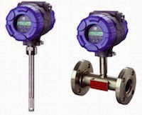
Thermal Dispersion Flow and Level Technology

thermal dispersion instruments
Thermal dispersion level and flow
instruments (courtesy of Magnetrol)
Thermal dispersion instruments work on the basis of heat transfer. The sensing probe consists of two separate components, both RTDs (temperature detectors). One RTD is used as the reference point and measures the temperature of the fluid right where the probe is immersed. The second RTD is self-heated to a known temperature and maintained. A resulting a temperature differential is created between the two RTDs. By varying the power to the self-heated RTD, the set point can be changed which allows the user to set the instrument for a specific application.

Convective heat is the mechanism of heat transfer for thermal technology level switches based on the principle that a liquid has a thermal conductivity far greater than the thermal conductivity of its corresponding vapor. When the sensor is dry, there is a temperature difference between the two sensors. When fluid comes in contact with both RTDs, there is a cooling effect as the liquid absorbs the heat from the self-heater RTD. The resulting temperature differential drops, and creates a point for high level reference. When the level drops and the sensor goes dry, the temperature difference increases again. The instrument electronics senses the increase in temperature difference and provides a low level reference.

When used for flow applications, the temperature difference under a low flow or no flow condition is controlled by the set point. As the flow rate increases, the sensing RTD is cooled by the fluid moving past the heated sensor - the greater the flow, the greater the cooling. Conversely, the reduction in the temperature differential between the two RTDs indicates that the flow rate is exceeding the set point of the instrument.

Float Operated Level Switch Fundementals

Float Level Switch
Float Level Switch
(courtesy of Magnetrol)

Float operated level switches are suitable for use on clean liquid applications alarm, pump control and safety shutdown applications.

These float type units are typically designed, fabricated and certified to compliance with ASME B31.3 specifications.

The design of float operated level switches is based upon the principle that a magnetic field will penetrate non-magnetic materials such as 316 stainless steel. In the case of a float type level switch, the float moves a magnetic attraction sleeve within a non-magnetic enclosing tube which in turn trips an electrical switch mechanism. The enclosing tube of housing provides a pressure seal for the chamber as well as the process.

As the liquid level rises in the chamber (refer to Figure 1), the float moves the magnetic attraction sleeve up within the enclosing tube, and into the field of the switch mechanism magnet. Resultingly, the magnet is drawn in tightly to the enclosing tube causing the switch to trip, “making” or “breaking” the electrical circuit.

As the liquid level falls, the float drops and moves the attraction sleeve out of the magnetic field, releasing the switch at a predetermined “low level” (refer to Figure 2). The tension spring ensures the return of the switch in a snap action.

Measuring Flow - The Transit-Time Difference Method

transit-time difference method
Transit-time difference Method
(courtesy of FLEXIM)

The Transit-Time Difference method exploits the fact that the transmission speed of an ultrasonic signal depends on the flow velocity of the carrier medium.

Similar to a swimmer swimming against the current, an ultrasonic signal moves slower against the flow direction of the medium than when in flow direction.

The Measurement Principle

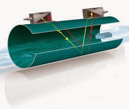
transit-time difference method
Diagram of FLEXIM transit-time
difference flow meter design.
For the measurement, two ultrasonic pulses are sent through the medium, one in the flow direction, and a second one against it. The transducers are alternatively working as an emitter and a receiver.

The transit-time of the ultrasonic signal propagating in the flow direction is shorter than the transit-time of the signal propagating against the flow direction. A transit-time difference, Δt, can thus be measured and allows the determination of the average flow velocity based on the propagation path of the ultrasonic signals.

An additional profile correction is performed by proprietary FLEXIM algorithms, to obtain an exceptional accuracy on the average flow velocity on the cross-section of the pipe - which is proportional to the volume flow.

Since ultrasounds propagate in solids, the transducers can be mounted onto the pipe.

The measurement is therefore non-intrusive, and thus no cutting or welding of pipes is required for the installation of the transducers.


Cycle Chargers - GlobalCharge Remote Power Systems by Global Thermoelectric

Cycle Chargers are the most fuel-efficient remote power system available today. They offer the highest efficiency of any prime remote power system and represent some of the toughest equipment on the market. Cycle Chargers are designed for long-term unattended operation, but can also be effective in support of grid supply. 

Global Thermoelectric, a leader in remote power systems, offers GlobalCharge - a fully self-contained remote power system offering continuous prime power from 300 Watts to 6000 Watts.

GlobalCharge is a self-contained remote power system that is ideal for applications where fuel consumption is a priority, or where only liquid fuel is available.

The technology associated with the charging system is proven as it has been used in specialized applications for over 15 years in the military, coast guard and border control. Global Thermoelectric has adapted this technology for use in industrial applications.

The result is a quiet, discreet product that operates reliably in areas where site access is difficult and site visits less frequent.


For more information contact:

M.S. Jacobs
800-348-0089
www.msjacobs.com

Magnetrol Hygienic Level Control Solutions

Here is a short video that illustrates the use of several level control technologies - guided radar level, ultrasonic level and thermal dispersion -  in hygienic applications.

The video shows us the benefits of each technology and where the Eclipse, Echotel and Thermatel controls are typically used.


For more information on level control in Western PA and West Virginia, contact MS Jacobs at 800-348-0089 or www.msjacobs.com

When to Use Pressure Gauge Accessories

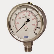
pressure gauge
Pressure Gauge (Wika)
Gauge accessories are designed to complement a pressure gauge in order to enhance and maximize its performance. Based on the application, pressure gauge accessories may never be required; however, protecting the pressure gauge from abnormal conditions is the most common reason for choosing to use a gauge accessory. Pressure spikes, temperature fluctuations and corrosion are leading causes for premature gauge failure. Your application may benefit from a gauge accessory.

Accessories for a pressure gauge may be the extra step needed for a successful, proactive, preventative maintenance program and for extending the life of pressure gauges in environments like oil and gas, petrochemical, and chemical plants. When a pressure gauge is paired with a mini-siphon, the gauge is protected from harmful steam, vapors and liquids. When a pressure gauge is paired with an overpressure protector, the gauge is protected from pressures exceeding its maximum pressure rating. When a pressure gauge is paired with a diaphragm seal, the gauge is protected from hot, viscous, contaminated or corrosive media. When a pressure gauge is paired with a snubber, the gauge is protected from pressure pulses.

Volume Booster Working Principle

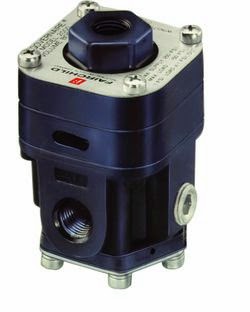
Pneumatic Volume Booster
(Fairchild)
A pneumatic air volume booster reproduce a low flow control signal with a higher regulated flow output pressure. It uses an unregulated input pressure to maintain a regulated output pressure under flowing and non-flowing conditions.

The volume booster is connected to the supply line and the output plumbing. It receives a pneumatic control signal, however, from another device, such as a transducer, valve positioner or other control means.

This pneumatic signal controls the pressure into and out of the booster, while allowing the booster to flow the maximum volume of the supply line. Boosters may also be referred to as pilot-operated regulators, as your control or pilot signal maintains the pressure control.

The regulated output of a pneumatic air volume booster can be any of the following:

      • A direct reproduction of the pneumatic control signal
      • A multiple of the pneumatic control signal 
      • A fraction of the pneumatic control signal

The volume booster ratio is the multiplier or divider of signal pressure to output pressure. For example, a 2:1 ratio means output pressure is 1/2 the signal pressure. Similarly, a 2:1 ratio would provide output pressure twice the signal pressure. Note, however, the output pressure can never exceed the supply pressure to the booster.

Often the signal pressure is lower than the supply pressure because a control device (valve positioner, I/P, etc.) will only handle a lower supply pressure.