
Showing posts with label Magnetrol. Show all posts

Guided Wave Radar to Lower Power Plant Costs

power plant
Reducing costs at power plants.
For most power plant operators, fuel expenditures account for seventy to eighty percent of production costs and millions of dollars per year. In fact improving heat rate one percent could generate five hundred thousand dollars an annual savings for five hundred megawatt power point.

To contain fuel costs, power plants must maximize the efficiency of their feed water heaters. That's why many companies today are focusing on improving heat rate as a way to use their feed water heaters more effectively, and significantly reduce their fuel costs.
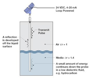
guided wave radar
Guided wave radar
principle of operation
.
Heat rate is a measure of how efficiently a power plant uses heat energy. You can measure heat rate by the number of BTU’s your plant requires to generate a kilowatt hour of energy. As you're heat rate goes up so do you're fuel costs.

The condenser is the beginning of the feed water heaters process, where condensed steam from the feed water heater drains, and HP, IP and LP turbines is routed through successive feed water heaters. At the same time,  extractions steam from your turbines reaches the appropriate feed water heaters and the transfer of energy takes place.

Maintaining accurate and reliable level control throughout this cycle is critical to achieving the final feed water heater temperature that your process requires.

Let's take a closer look at how this works.  Feed water heaters use the heat of condensation to preheat water to the correct temperature for the boiler. During this process, shell and tube heat exchangers allow feed water to pass through the tube side and extract steam from the turbine to the shell side.

The primary benefit of this process is that the feed water heater decreases the fuel costs by using recovered energy, rather than costly hot gas, to heat the water.

Achieving optimum water level in a feed water heater is a critical component of maximizing energy transfer and minimizing controllable losses.

There are normally six to seven stages of feed water heating. Making an investment in level control can help you achieve optimum heat transfer and improved terminal temperature difference to provide a significant return on investment.

guided wave radar
Guided wave radar
transmitter
(courtesy of
Magnetrol)
With a guided wave radar level control, you can optimize the condensing zone of your feed water heater to deliver accurate level control, maximize energy transfer, and minimize undue wear and tear. This can help you generate the savings needed to recover your investment.

Older level technologies, such as differential pressure, magnetostrictive, or RF capacitance and torque tubes are vulnerable to process conditions and induced instrument errors, such as shifts in specific gravity and mechanical or electronic drift.

In contrast, guided wave radar provides a truly reliable level measurement solution for feed water heaters. Guided wave radar performance is virtually unaffected by process variations and gives you a superior degree of accurate and reliable continuous level measurement without the need for calibration or gravity corrections.

With superior signal performance and advanced diagnostics, guided wave radar delivers premier level control for feed water heaters, as well as a broad range of challenging applications, such as condenser hot wells, deaerators, and cooling tower basins.

Combining a magnetic level indicator with guided wave radar merges the operating systems of a conventional flowed base magnetic level indicator with a leading edge solution. This allows you to effectively measure low dielectric media, high temperature, and high pressure process conditions and media, with shifting specific gravity and dielectric values accurately and repeatedly. The result is a diverse and redundant level measurement solution in a single chamber design.

For more information contact:

M.S. Jacobs and Associates
Phone: 800-348-0089
Fax: 412-279-4810
Email: msjacobs@msjacobs.com
www.msjacobs.com
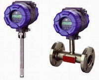
Thermal Dispersion Flow and Level Technology

thermal dispersion instruments
Thermal dispersion level and flow
instruments (courtesy of Magnetrol)
Thermal dispersion instruments work on the basis of heat transfer. The sensing probe consists of two separate components, both RTDs (temperature detectors). One RTD is used as the reference point and measures the temperature of the fluid right where the probe is immersed. The second RTD is self-heated to a known temperature and maintained. A resulting a temperature differential is created between the two RTDs. By varying the power to the self-heated RTD, the set point can be changed which allows the user to set the instrument for a specific application.

Convective heat is the mechanism of heat transfer for thermal technology level switches based on the principle that a liquid has a thermal conductivity far greater than the thermal conductivity of its corresponding vapor. When the sensor is dry, there is a temperature difference between the two sensors. When fluid comes in contact with both RTDs, there is a cooling effect as the liquid absorbs the heat from the self-heater RTD. The resulting temperature differential drops, and creates a point for high level reference. When the level drops and the sensor goes dry, the temperature difference increases again. The instrument electronics senses the increase in temperature difference and provides a low level reference.

When used for flow applications, the temperature difference under a low flow or no flow condition is controlled by the set point. As the flow rate increases, the sensing RTD is cooled by the fluid moving past the heated sensor - the greater the flow, the greater the cooling. Conversely, the reduction in the temperature differential between the two RTDs indicates that the flow rate is exceeding the set point of the instrument.

Float Operated Level Switch Fundementals

Float Level Switch
Float Level Switch
(courtesy of Magnetrol)

Float operated level switches are suitable for use on clean liquid applications alarm, pump control and safety shutdown applications.

These float type units are typically designed, fabricated and certified to compliance with ASME B31.3 specifications.

The design of float operated level switches is based upon the principle that a magnetic field will penetrate non-magnetic materials such as 316 stainless steel. In the case of a float type level switch, the float moves a magnetic attraction sleeve within a non-magnetic enclosing tube which in turn trips an electrical switch mechanism. The enclosing tube of housing provides a pressure seal for the chamber as well as the process.

As the liquid level rises in the chamber (refer to Figure 1), the float moves the magnetic attraction sleeve up within the enclosing tube, and into the field of the switch mechanism magnet. Resultingly, the magnet is drawn in tightly to the enclosing tube causing the switch to trip, “making” or “breaking” the electrical circuit.

As the liquid level falls, the float drops and moves the attraction sleeve out of the magnetic field, releasing the switch at a predetermined “low level” (refer to Figure 2). The tension spring ensures the return of the switch in a snap action.

Magnetrol Hygienic Level Control Solutions

Here is a short video that illustrates the use of several level control technologies - guided radar level, ultrasonic level and thermal dispersion -  in hygienic applications.

The video shows us the benefits of each technology and where the Eclipse, Echotel and Thermatel controls are typically used.


For more information on level control in Western PA and West Virginia, contact MS Jacobs at 800-348-0089 or www.msjacobs.com

Magnetrol ECHOTEL Ultrasonic Level Switch Operating Principle

The Magnetrol ECHOTEL utilizes ultrasonic energy to detect the presence or absence of liquid in a single or dual point transducer. Ultrasonic contact level technology uses high-frequency sound waves that are easily transmitted across a transducer gap in the presence of a liquid media, but are attenuated when the gap is dry. The ECHOTEL switches use an ultrasonic frequency of 2 MHz to perform this liquid level measurement in a wide variety of process media and application conditions.

The transducer uses a pair of piezoelectric crystals that are encapsulated in epoxy at the tip of the transducer. The crystals are made of a ceramic material that vibrates at a given frequency when subjected to an applied voltage. The transmit crystal converts the applied voltage from the electronics into an ultrasonic signal. When liquid is present in the gap, the receive crystal senses the ultrasonic signal from the transmit crystal and converts it back to an electrical signal. This signal is sent to the electronics to indicate the presence of liquid in the transducer gap. When there is no liquid present, the ultrasonic signal is attenuated and is not detected by the receive crystal.


For more information on industrial level control, contact M.S. Jacobs and Associates.