 |
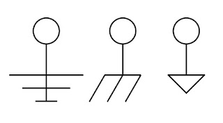
| Electrical Drawing Symbols for Ground |
The white paper that I have included below was produced by the folks at Acromag, a world class manufacturer of signal conditioners and other industrial I/O devices. They have done a fantastic job of presenting technical subject matter in a compact and very understandable form. The subjects covered in the series include:
- Ground as protection
- How a ground fault circuit interrupter (GFCI) works
- Ground as a voltage stabilizer and transient limiter
- Tips on improving safety and signal integrity
- The importance of circuit grounding
- Description of the US AC power system and its use of earth ground
Product specialists are always on hand to discuss and solve your process measurement and control issues. Combine the process knowledge of the on site stakeholder with the product and application expertise of the professional sales engineer to produce the best outcomes.