When to Use Pressure Gauge Accessories

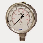
pressure gauge
Pressure Gauge (Wika)
Gauge accessories are designed to complement a pressure gauge in order to enhance and maximize its performance. Based on the application, pressure gauge accessories may never be required; however, protecting the pressure gauge from abnormal conditions is the most common reason for choosing to use a gauge accessory. Pressure spikes, temperature fluctuations and corrosion are leading causes for premature gauge failure. Your application may benefit from a gauge accessory.

Accessories for a pressure gauge may be the extra step needed for a successful, proactive, preventative maintenance program and for extending the life of pressure gauges in environments like oil and gas, petrochemical, and chemical plants. When a pressure gauge is paired with a mini-siphon, the gauge is protected from harmful steam, vapors and liquids. When a pressure gauge is paired with an overpressure protector, the gauge is protected from pressures exceeding its maximum pressure rating. When a pressure gauge is paired with a diaphragm seal, the gauge is protected from hot, viscous, contaminated or corrosive media. When a pressure gauge is paired with a snubber, the gauge is protected from pressure pulses.
Volume Booster Working Principle

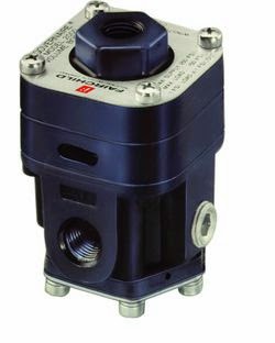
Pneumatic Volume Booster
(Fairchild)
A pneumatic air volume booster reproduce a low flow control signal with a higher regulated flow output pressure. It uses an unregulated input pressure to maintain a regulated output pressure under flowing and non-flowing conditions.

The volume booster is connected to the supply line and the output plumbing. It receives a pneumatic control signal, however, from another device, such as a transducer, valve positioner or other control means.

This pneumatic signal controls the pressure into and out of the booster, while allowing the booster to flow the maximum volume of the supply line. Boosters may also be referred to as pilot-operated regulators, as your control or pilot signal maintains the pressure control.

The regulated output of a pneumatic air volume booster can be any of the following:

      • A direct reproduction of the pneumatic control signal
      • A multiple of the pneumatic control signal 
      • A fraction of the pneumatic control signal

The volume booster ratio is the multiplier or divider of signal pressure to output pressure. For example, a 2:1 ratio means output pressure is 1/2 the signal pressure. Similarly, a 2:1 ratio would provide output pressure twice the signal pressure. Note, however, the output pressure can never exceed the supply pressure to the booster.

Often the signal pressure is lower than the supply pressure because a control device (valve positioner, I/P, etc.) will only handle a lower supply pressure.


Solenoid Valve Application Tip

solenoid valves
Solenoid Valves
(courtesy of GC Valve)
Mechanical & Materials Considerations

Solenoid valves are your fastest-acting option when controlling flow. They can be repaired in-line (without breaking plumbing connections in most designs), and they can be less costly than other electrically operated valves.

But there are a few measures that can increase your satisfaction with solenoid valves:
Install strainers or filters to prevent foreign materials from entering the valve and interfering with operation.
  • Avoid Teflon tape; those stringy leftover pieces can travel downstream and hang up in the valve.
  • Use pipe dope sparingly; globs of it in the line can affect solenoid valves and other control elements.
  • Add check valves to your design if it is important to prevent back flow through the solenoid valve.
  • Consider plumbing solenoid valves in series (double-block) where any leakage is unacceptable.
  • Ask for a plated operator to protect special grades of stainless steel from corrosion.
And be sure to let your representative know about everything in the process fluid. Additives in air, water or other fluids can change the soft-seal requirements.

For more information, or assistance with selecting solenoid valves, contact:

M.S. Jacobs
810 Noblestown Road
Pittsburgh, Pa 15205
Toll free (800) 348-0089
www.msjacobs.com
Email: msjacobs@msjacobs.com

Process Control Products for Shale Gas Extraction, Processing and Transport


The Marcellus Formation, one of the largest shale gas resources in North America, sits directly under much of M.S. Jacobs area of coverage. Many of the product lines they handle are needed in the extraction, processing and transport of the shale gas.

Global Thermoelectric TEG (thermoelectric generator)
Global Thermoelectric TEG
(thermoelectric generator)
The Global Thermoelectric TEG (thermoelectric generator) is a product M.S. Jacobs provides for “upstream” use on the production well pad. It is used to supply remote power and is preferred in colder climates because of its reliability, it has no moving parts, and its operating principle. A thermoelectric generator converts heat directly into electricity. As heat moves from a gas burner through a thermoelectric module, it causes an electrical current to flow. Solar was the preferred source of power for many of the production companies from Texas and Oklahoma. That was until they experienced the harsh cold winter in Pennsylvania without days of sun which led to dead batteries and no data/control on the well.

Flexim Midstream Gas Meters
Other products M.S. Jacobs provides for "midstream" use are Flexim ultrasonic clamp-on flowmeters. These are being used as check meters at midstream processing facilities and compressor stations to measure large volumes of gas. They are also being used to help balance the load to the compressors. Other applications are on gas storage wells that are filled in the summer and pumped out in the fall-winter, taking advantage of the bi-directional measurement capability of the meter.

M.S. Jacobs also provides Magnetrol level controls and Orion visual level indicators for various level applications as well as valves and controls on other midstream and downstream applications.

There has been an explosion of midstream processing facilities in this area. Many processing companies have set up facilities to strip the propane and butane from the rich Marcellus “wet gas” and send the methane downstream for use in our homes. M.S. Jacobs has become a primary partner to many of these processing companies because of our application skills, local inventory, and support.

Magnetrol ECHOTEL Ultrasonic Level Switch Operating Principle

The Magnetrol ECHOTEL utilizes ultrasonic energy to detect the presence or absence of liquid in a single or dual point transducer. Ultrasonic contact level technology uses high-frequency sound waves that are easily transmitted across a transducer gap in the presence of a liquid media, but are attenuated when the gap is dry. The ECHOTEL switches use an ultrasonic frequency of 2 MHz to perform this liquid level measurement in a wide variety of process media and application conditions.

The transducer uses a pair of piezoelectric crystals that are encapsulated in epoxy at the tip of the transducer. The crystals are made of a ceramic material that vibrates at a given frequency when subjected to an applied voltage. The transmit crystal converts the applied voltage from the electronics into an ultrasonic signal. When liquid is present in the gap, the receive crystal senses the ultrasonic signal from the transmit crystal and converts it back to an electrical signal. This signal is sent to the electronics to indicate the presence of liquid in the transducer gap. When there is no liquid present, the ultrasonic signal is attenuated and is not detected by the receive crystal.


For more information on industrial level control, contact M.S. Jacobs and Associates.

Introduction to Level Measurement

In many industrial processes, the measurement of level is critical. Depending on the nature of the material being measured, this can be a simple or complex task. Several different technologies for sensing level are briefly explained here.
Gauge or Sightglass
Gauge or Sightglass

Level Gauges or Sightglasses

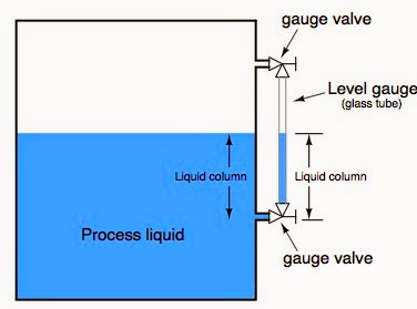
The simplest form of level measurement for direct measurement of level (almost always visually)  in a vessel. A level gauge (sightglass) is usually a clear tube connected to the a vessel at the highest and lowest part of the level range. The fluid level inside the vessel will be at the same hight as the level in the tube. 

Control Valve Selection - 8 Things to Remember

control valve
Cashco Control Valve
Choosing an improperly applied sized or improperly sized control valve can have serious consequences on operation, productivity and most important, safety. Here is a quick checklist of basics that need to be considered:

  1. Control valves are not intended to be a an isolation valve and should not be used for isolating a process. 
  2. Always carefully select the correct materials of construction. Take into consideration the parts of the valve that comes in to contact with the process media such as the valve body, the seat and any other "wetted" parts. Consider the operating pressure and operating temperature the control valve will see. Finally, also consider the ambient atmosphere and any corrosives that can occur and effect the exterior of the valve. 
  3. Put your flow sensor upstream of the control valve. Locating the flow sensor downstream of the control valve exposes it to an unstable flow stream which is caused by turbulent flow in the valve cavity.
  4. Factor in the degree of control you need and make sure your valve is mechanically capable. Too much dead-band leads to hunting and poor control. Dead-band is roughly defined as the amount of control signal required to affect a change in valve position. It is caused by worn, or loosely fitted mechanical linkages, or as a function of the controller setting. It can also be effected by the tolerances from mechanical sensors, friction inherent in the the valve stems and seats, or from an undersized actuator. 
  5. Consider stiction. The tendency for valves that have had very limited travel, or that haven't moved at all, to "stick" is referred to as stiction. It typically is caused by the valves packing glands, seats or the pressure exerted against the disk. To overcome stiction, additional force needs to be applied by the actuator, which can lead to overshoot and poor control.
  6. Tune your loop controller properly. A poorly tuned controller causes overshoot, undershoot and hunting. Make sure your proportional, integral, and derivative values are set).  This is quite easy today using controllers with advanced, precise auto-tuning features that replaced the old fashioned trial and error loop tuning method.
  7. Don't over-size your control valve. Control valves are frequently sized larger than needed for the flow loop they control. If the control valve is too large, only a small percentage of travel is used (because a small change in valve position has a large effect on flow), which in turn makes the valve hunt. This causes excessive wear. Try to always size a control valve at about 70%-90% of travel.
  8. Think about the type of control valve you are using and its inherent flow characteristic. Different types of valve, and their disks, have very different flow characteristics (or profiles). The flow characteristic can be generally thought of as the change in rate of flow in relationship to a change in valve position. Globe control valves have linear characteristics which are preferred, while butterfly and gate valves have very non-linear flow characteristics, which can cause control problems.  In order to create a linear flow characteristic through a non-linear control valve, manufacturers add specially designed disks or flow orifices which create a desired flow profile.
These are just a few of the more significant criteria to consider when electing a control valve. You should always discuss your application with an experienced application expert before making your final selection.