Measuring Flow - The Transit-Time Difference Method

transit-time difference method
Transit-time difference Method
(courtesy of FLEXIM)

The Transit-Time Difference method exploits the fact that the transmission speed of an ultrasonic signal depends on the flow velocity of the carrier medium.

Similar to a swimmer swimming against the current, an ultrasonic signal moves slower against the flow direction of the medium than when in flow direction.

The Measurement Principle
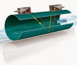
transit-time difference method
Diagram of FLEXIM transit-time
difference flow meter design.
For the measurement, two ultrasonic pulses are sent through the medium, one in the flow direction, and a second one against it. The transducers are alternatively working as an emitter and a receiver.

The transit-time of the ultrasonic signal propagating in the flow direction is shorter than the transit-time of the signal propagating against the flow direction. A transit-time difference, Δt, can thus be measured and allows the determination of the average flow velocity based on the propagation path of the ultrasonic signals.

An additional profile correction is performed by proprietary FLEXIM algorithms, to obtain an exceptional accuracy on the average flow velocity on the cross-section of the pipe - which is proportional to the volume flow.

Since ultrasounds propagate in solids, the transducers can be mounted onto the pipe.

The measurement is therefore non-intrusive, and thus no cutting or welding of pipes is required for the installation of the transducers.
Cycle Chargers - GlobalCharge Remote Power Systems by Global Thermoelectric

Cycle Chargers are the most fuel-efficient remote power system available today. They offer the highest efficiency of any prime remote power system and represent some of the toughest equipment on the market. Cycle Chargers are designed for long-term unattended operation, but can also be effective in support of grid supply. 

Global Thermoelectric, a leader in remote power systems, offers GlobalCharge - a fully self-contained remote power system offering continuous prime power from 300 Watts to 6000 Watts.

GlobalCharge is a self-contained remote power system that is ideal for applications where fuel consumption is a priority, or where only liquid fuel is available.

The technology associated with the charging system is proven as it has been used in specialized applications for over 15 years in the military, coast guard and border control. Global Thermoelectric has adapted this technology for use in industrial applications.

The result is a quiet, discreet product that operates reliably in areas where site access is difficult and site visits less frequent.


For more information contact:

M.S. Jacobs
800-348-0089
www.msjacobs.com

Magnetrol Hygienic Level Control Solutions

Here is a short video that illustrates the use of several level control technologies - guided radar level, ultrasonic level and thermal dispersion -  in hygienic applications.

The video shows us the benefits of each technology and where the Eclipse, Echotel and Thermatel controls are typically used.


For more information on level control in Western PA and West Virginia, contact MS Jacobs at 800-348-0089 or www.msjacobs.com

Clamp-on Ultrasonic Flow Measurement Advantages in Pipes and Storage Tanks

Flexim clamp-on ultrasonic flow meter
Clamp-on ultrasonic flow meter
(courtesy of Flexim)
In order to accurately pump and store fluids, reliable and accurate flow measurement is essential. Intrusive flow meters such as turbine meters and orifice plates are problematic when it comes to maintenance and long-term accuracy.

A better solution is a clamp-on, externally mounted, ultrasonic flow meter. These types of meters simply mount right to the outside of the process piping and do not expose the sensor to the process media. Nor do they require the pipe of vessel to be open for maintenance. Furthermore, they provide high accuracy and repeatability needed for leak detection and minimization of product losses.

Another advantage of using clamp-on flow meters is to use sonic velocity to determine what hydrocarbons are flowing through the pipe. Sonic velocity, when corrected for temperature change, is a good way to distinguish most hydrocarbons. By comparing the actual sonic velocity in a given application, and comparing it to known sonic velocity data, hydrocarbons at given temperatures can be identified.

This comes in particularly helpful in detecting interface changes. Different product batches are easily recognized by the meter. As interface changes are detected with a high degree of sensitivity, product mixups are significantly reduced.

Additional advantages of clamp-on, ultrasonic flow meters:

  • No wear and tear - no clogging effects
  • Quick and accurate detection of Interface changes - reducing amount of product mixing
  • Accurate measurement on thick walled pipes and exotic pipe materials

Happy Holidays from M.S. Jacobs and Associates

On behalf of everyone at M.S. Jacobs and Associates, we wish you a very Happy Holiday Season and a prosperous New Year!

When to Use Pressure Gauge Accessories

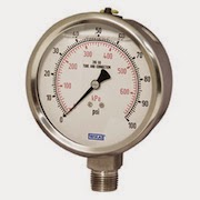
pressure gauge
Pressure Gauge (Wika)
Gauge accessories are designed to complement a pressure gauge in order to enhance and maximize its performance. Based on the application, pressure gauge accessories may never be required; however, protecting the pressure gauge from abnormal conditions is the most common reason for choosing to use a gauge accessory. Pressure spikes, temperature fluctuations and corrosion are leading causes for premature gauge failure. Your application may benefit from a gauge accessory.

Accessories for a pressure gauge may be the extra step needed for a successful, proactive, preventative maintenance program and for extending the life of pressure gauges in environments like oil and gas, petrochemical, and chemical plants. When a pressure gauge is paired with a mini-siphon, the gauge is protected from harmful steam, vapors and liquids. When a pressure gauge is paired with an overpressure protector, the gauge is protected from pressures exceeding its maximum pressure rating. When a pressure gauge is paired with a diaphragm seal, the gauge is protected from hot, viscous, contaminated or corrosive media. When a pressure gauge is paired with a snubber, the gauge is protected from pressure pulses.

Volume Booster Working Principle

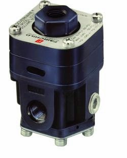
Pneumatic Volume Booster
(Fairchild)
A pneumatic air volume booster reproduce a low flow control signal with a higher regulated flow output pressure. It uses an unregulated input pressure to maintain a regulated output pressure under flowing and non-flowing conditions.

The volume booster is connected to the supply line and the output plumbing. It receives a pneumatic control signal, however, from another device, such as a transducer, valve positioner or other control means.

This pneumatic signal controls the pressure into and out of the booster, while allowing the booster to flow the maximum volume of the supply line. Boosters may also be referred to as pilot-operated regulators, as your control or pilot signal maintains the pressure control.

The regulated output of a pneumatic air volume booster can be any of the following:

      • A direct reproduction of the pneumatic control signal
      • A multiple of the pneumatic control signal 
      • A fraction of the pneumatic control signal

The volume booster ratio is the multiplier or divider of signal pressure to output pressure. For example, a 2:1 ratio means output pressure is 1/2 the signal pressure. Similarly, a 2:1 ratio would provide output pressure twice the signal pressure. Note, however, the output pressure can never exceed the supply pressure to the booster.

Often the signal pressure is lower than the supply pressure because a control device (valve positioner, I/P, etc.) will only handle a lower supply pressure.