New Product From Cameron - CamCor Coriolis Flow Meters

Industrial Coriolis Flow Meter - Cameron
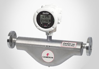
CamCor Pro - Industrial Coriolis Flow Meter
Courtesy Cameron
Whether it's high viscosity crude oils, ultra-low flow conditions or applications at the extremes of temperature, Cameron's new CamCor™ range of Coriolis flow meters deliver value beyond the whole-life operational benefits associated with non-mechanical architectures.

CamCor comes in two architectures, CamCor CT for custody transfer, where the emphasis particularly is on high accuracy, and the Cameron CamCor PRO for process operations.

CamCor CT offers flow rate accuracy of ± 0.1% for liquids, as a result of its deep “U” shaped dual sensors, with outstanding zero stability performance (0.071 lb/min for 2” model). The range includes models purpose-designed for application extremes, covering temperatures from -200°C (Cryogenic/ LNG) up to 350°C. Nominal sensor sizes go from less than 2mm to 250mm, with 1/4” to 10” end connections, offered in ANSI class 150 to 900, other flange types, threaded, or Tri-Clover.

The unit is manufactured of 316/316L stainless steel and Hastelloy Alloy C22.

The CamCor PRO Series possesses a flow rate turndown ration up to 50:1, flow rate accuracy of
+/- 0.2% and density accuracy of +/- 0.003 g/ml. It comes with the same transmitter, output, communications, diagnostics and configuration as the CamCor CT and is available in four nominal sensor sizes, from 6mm to 50mm, with 1/2” to 2” end connections in ANSI flanges and Tri-Clover.

Review the product brochure below, or contact a product specialist for more details or a discussion of your application.


New Stainless Steel Fuel Control Regulator From Fairchild

Cutaway of the Model 67
Precision Stainless Steel Fuel Control Regulator
Courtesy Fairchild Industrial Products
Fuel control is an essential and critical variable for engine and combustion testing. Fairchild Industrial Products Company has developed a stainless steel high precision fuel control regulator for use in engine testing. The new Model 67 combines durability, flexibility, and accuracy into a single product to improve your engine testing process. Some of the basic benefits:

High level of accuracy.

Reliability in engine under test fuel supply.


Stainless steel construction for wide range fuel suitability.

Constant output, even with fluctuating supply pressure or downstream pulsation.

Design allows for quick fuel changeover.

Washdown and internal purge capability.

Review the literature below and contact a product specialist for more detailed information, or to discuss your application.


Multivariable Vortex Flowmeter

Industrial flowmeter
Multivariable Vortex Flowmeter
Courtesy Azbil North America
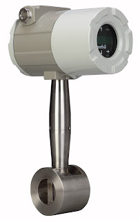
A new multivariable vortex flowmeter has recently been added to the product line at MS Jacobs & Associates. It is intended for industrial process measurement and control. The AX Series, from Azbil North America, utilizes a vortex shedding velocity sensor, solid state pressure transducer, and resistance temperature detector in a single unit to allow accurate measurement of mass flow in gases, liquids and steam. The combination of multiple variable measurement in a single package simplifies installation and setup cost, while reducing potential leakage paths of an arrangement employing separate instruments for each variable. The AX Series is available for in-line or insertion installation. Your product sales engineer can provide a sizing guide and other assistance in selecting and configuring the best product for your application.


Selecting the Right Valve Type - Gate Valves

When it comes to controlling flow in an industrial fluid handling system, there are more choices than you can count. The journey of focusing in on the best option for your application can be shortened by employing some coarse filters to the vast array of available products and technologies, discarding choices that do not meet the basic criteria deemed essential to a successful project.

A common type of industrial valve is the gate valve. It regulates fluid flow by sliding a round or rectangular wedge, known as the gate or disc, in the flow path of the fluid. When the gate is fully retracted from the fluid path, flow is enabled to its fullest. Gate valves close by sliding the gate, which is commonly attached to a threaded shaft of other similar mechanism, into the path of the flow until it is fully obstructed. It is the movement of the gate, combined with the way in which a gate valve is constructed, that attributes this valve class with its positive and negative values.

Positives for gate valves:

  • When fully open, there is low resistance to fluid flow. The opening in the valve tends to mimic the cross sectional characteristics of connected piping and fluid can flow through the valve without a directional change.
  • Changing the gate position (opening or closing the valve) does not require as much force or power as some other valve types, due to the gate movement being perpendicular to the flow direction.
  • Gate valves work in both directions. The flow in the connected line can be reversed and the valve function is unimpaired.
  • The gate valve assembly tends to be shorter in length along the path of flow than some other designs.
  • Gate Valves in Pipeline
    Gate Valves in Process Pipeline
  • The rate of closure is generally slow, providing a graduated reduction in fluid movement and reduced physical shock to the piping system.
Operating or construction characteristics that may be an advantage to gate valve employment on one application may prove a disadvantage in another.

“Not so positives” for gate valves:

  • When the valve is open, the seals are exposed to the fluid flow. Foreign material, even elements of the process fluid, can deteriorate or contaminate the seals and impact the sealing of the valve when closed.
  • The gate valve opens at a comparatively slow rate, making it unsuitable for applications that may require rapid or immediate shutoff.
  • The service and maintenance space requirements, often extending overhead of the valve, can be substantial and may impact the ability to locate the assembly where desired.
  • Gate valves are not well suited for throttling fluid flow. Fluid flow through a partially open valve of this type may cause the gate to vibrate.

There are certainly more elements involved in proper valve selection than are shown here, but this quick check may help you focus on gate valves or another technology for further consideration. It is always beneficial to bring in experts and those with experience to participate in the selection process.

Guided Wave Radar to Lower Power Plant Costs

power plant
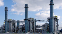
Reducing costs at power plants.
For most power plant operators, fuel expenditures account for seventy to eighty percent of production costs and millions of dollars per year. In fact improving heat rate one percent could generate five hundred thousand dollars an annual savings for five hundred megawatt power point.

To contain fuel costs, power plants must maximize the efficiency of their feed water heaters. That's why many companies today are focusing on improving heat rate as a way to use their feed water heaters more effectively, and significantly reduce their fuel costs.

guided wave radar
Guided wave radar
principle of operation
.
Heat rate is a measure of how efficiently a power plant uses heat energy. You can measure heat rate by the number of BTU’s your plant requires to generate a kilowatt hour of energy. As you're heat rate goes up so do you're fuel costs.

The condenser is the beginning of the feed water heaters process, where condensed steam from the feed water heater drains, and HP, IP and LP turbines is routed through successive feed water heaters. At the same time,  extractions steam from your turbines reaches the appropriate feed water heaters and the transfer of energy takes place.

Maintaining accurate and reliable level control throughout this cycle is critical to achieving the final feed water heater temperature that your process requires.

Let's take a closer look at how this works.  Feed water heaters use the heat of condensation to preheat water to the correct temperature for the boiler. During this process, shell and tube heat exchangers allow feed water to pass through the tube side and extract steam from the turbine to the shell side.

The primary benefit of this process is that the feed water heater decreases the fuel costs by using recovered energy, rather than costly hot gas, to heat the water.

Achieving optimum water level in a feed water heater is a critical component of maximizing energy transfer and minimizing controllable losses.

There are normally six to seven stages of feed water heating. Making an investment in level control can help you achieve optimum heat transfer and improved terminal temperature difference to provide a significant return on investment.

guided wave radar
Guided wave radar
transmitter
(courtesy of
Magnetrol)
With a guided wave radar level control, you can optimize the condensing zone of your feed water heater to deliver accurate level control, maximize energy transfer, and minimize undue wear and tear. This can help you generate the savings needed to recover your investment.

Older level technologies, such as differential pressure, magnetostrictive, or RF capacitance and torque tubes are vulnerable to process conditions and induced instrument errors, such as shifts in specific gravity and mechanical or electronic drift.

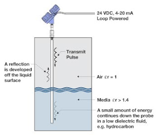
In contrast, guided wave radar provides a truly reliable level measurement solution for feed water heaters. Guided wave radar performance is virtually unaffected by process variations and gives you a superior degree of accurate and reliable continuous level measurement without the need for calibration or gravity corrections.

With superior signal performance and advanced diagnostics, guided wave radar delivers premier level control for feed water heaters, as well as a broad range of challenging applications, such as condenser hot wells, deaerators, and cooling tower basins.

Combining a magnetic level indicator with guided wave radar merges the operating systems of a conventional flowed base magnetic level indicator with a leading edge solution. This allows you to effectively measure low dielectric media, high temperature, and high pressure process conditions and media, with shifting specific gravity and dielectric values accurately and repeatedly. The result is a diverse and redundant level measurement solution in a single chamber design.

For more information contact:

M.S. Jacobs and Associates
Phone: 800-348-0089
Fax: 412-279-4810
Email: msjacobs@msjacobs.com
www.msjacobs.com
Introduction to Rotameters

rotameter
Rotameter
(courtesy of
King Instrument)
A rotameter is one particular type of variable area flowmeter that measures flow by varying the cross-sectional area a fluid or gas travels through in a closed tube.

Advantages
  • Requires no external power.
  • Is a simple device that can be easily manufactured out of inexpensive materials.
  • Linear scale.
  • The clear glass tube is resistant to thermal shock and chemical reaction.
Disadvantages
  • Must be mounted vertically, with designated top and bottom, and with the fluid flowing from bottom to top.
  • Graduations on a given rotameter are only accurate for a given substance at a given temperature. Separate rotameters must be used for fluids with different densities and viscosities, or multiple scales on the same rotameter must be used.
  • Resolution is relatively poor and gets worse near the bottom of the scale.
  • Oscillations of the float and parallax lend to reduced accuracy.
  • Difficult to automate - primarily a manual / visual device


For more information on rotameters, contact:

M.S. Jacobs and Associates, Inc.
810 Noblestown Road
Pittsburgh, Pa 15205
Toll free: 800 348 0089
Fax: 412-279-4810
Email: msjacobs@msjacobs.com
www.msjacobs.com

Basics of Infrared Flame Detection

flame detector
Triple IR flame detector
(courtesy if Sierra Monitor)
A flame detector is a specialized sensor used to detect and respond to the presence of a flame, and accordingly notify an operator, sound an alarm, close a fuel supply valve, shut down a pump, and turn on a fire suppression system. 

Flame detectors are fast acting and accurate, much more so than smoke or heat detectors because of the technology they employ. Some flame detectors can detect fires up to 215 feet away and be accurate enough to detect a 1 sq. foot gasoline pan at 215 feet in less than 5 seconds. 

One popular type of flame detection technology used is measuring infrared (IR) light coming from a source. This type of sensor monitors the infrared light spectrum for very specific patterns given off by hot gases. These hot gases are sensed by a specialized fire-fighting thermal imaging (thermographic) camera. 

One method of determining if a fire exists is by looking for the infrared peak of hot carbon dioxide (approximately 4.4 micrometers). Response times of a typical IR detector is 3–5 seconds. 

There is the possibility, however, of false alarms caused by background thermal radiation and other hot surfaces in the area. Another potential concern is with the formation of condensate on the flame detector's lens, which can greatly reduce its accuracy. Direct exposure to sunlight for these types of detectors can also be problematic. 

An approach to overcome these issues is with dual or triple IR sensors, which compare the threshold signal in two or three infrared ranges. Often one sensor looks at the 4.4 micrometer carbon dioxide (CO2) emission, while the other sensors looks at additional reference frequencies. Modern flame detector design allow users to select different sensitivity levels to ensure no other detectors cross-over detection zones. 

Additional important features to be considered are heated windows to eliminate condensation and icing, HART and Modbus capabilities for digital communications, low excitation power, and compact design. 

When selecting a flame detector for any application, it is important to make sure it is approved and certified for that specific use. Check for third party agency approval including FM, ATEX, IECEx, TUV, and CSA. These approvals and certifications assure the highest quality of products and performance.

Finally, the proper application of flame detectors is critical in many applications for the safety and protection of property and personnel. Therefore, it is always suggested that your application be discussed with a qualified application engineer