Automatic Self Cleaning Strainer for Fluid Processing

cutaway view of automatic self cleaning strainer
An automatic self-cleaning strainer is suitable for many
applications and reduces manual maintenance.
Strainers and other filtration equipment reduce the burden of targeted unwanted solids in a fluid system. Potentially damaging particulate material is trapped and held for removal from the system. Keeping fluid systems clean helps to maintain long term design performance and potentially extends the operating life of pumps, valves, and other mechanical devices in the system.

Strainers generally consist of a heavy duty housing and a contained screen with controlled opening size designed to disallow the passage of particles exceeding a targeted size. Trapped particulates remain on the screen, or within a shape created by the screen such as a basket (see basket strainer). The continuing collection of solids will eventually impede the free flow of the process fluid, so the strainer must be emptied or cleaned periodically. The frequency of cleaning is a function of the solids content of the incoming fluid and may not necessarily be a regular interval. A simple strainer, to be cleaned, requires temporary shutdown of the flow or bypass of process fluid around the strainer assembly. A duplex strainer consists of twin strainers, usually housed in a common assembly, with a diverter valve that allows the inlet flow to be directed to one of the strainers while closing off the other from the system. This allows for cleaning of one of the strainers while the other is in active service, maintaining continuous fluid flow.
A third solution provides the continuous operation of a duplex strainer, but without the need for manual cleaning. 
An automatic self-cleaning strainer, such as the MCS 500 from Eaton provides uninterrupted operation without a duplex configuration or regular manual cleaning. It's form is essentially a housed strainer with a built-in scraper blade that moves along the inlet surface of the strainer media, moving accumulated solids to a collection chamber at the bottom of the pressure housing. Automatic controls regulate the operation of the scraper and discharge valve on the purge chamber that removes the collected solids from the system. The automatic self-cleaning strainer provides a cost effective time saving solution for the filtration of compatible fluids.

More detail for the MCS 500 is provided below. Share your fluid filtration requirements and challenges with fluid processing specialists. Leverage your own process knowledge and experience with their product application expertise to develop effective solutions.

A Little History

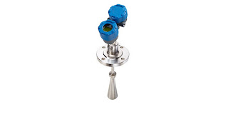
26 GHz radar level measurement transmitter
Pulsar® R86 Radar Level Transmitter
One of Magnetrol's recent innovations.
Some companies, through hard work, innovation, and good fortune, manage to stand the test of time and thrive for decades in a competitive environment. The manufacture of process measurement and control equipment and devices is an arena where standing still in the market is not a viable business strategy. Magnetrol has been helping process operators measure and control fluid level and flow for decades. The company recently posted an article on their own blog outlining a little of the company history as illustrated through product innovations. We include an excerpt from the blog below and encourage readers to share their fluid level and flow challenges with application specialists. Leveraging your own process knowledge and experience with their product application expertise to develop effective solutions.

This year marks the 85th anniversary of the founding of Magnetrol®. Since its very beginning, MAGNETROL has been a company focused on level and flow measurement innovation, designing cost-effective, cutting-edge solutions for its customers. In honor of 85 years of success, here’s a look back on some MAGNETROL highlights over the years. 
The Beginning
The history of MAGNETROL dates to 1932 as a Chicago-based manufacturer of boiler systems. The first MAGNETROL level control was born when the founding company, Schaub Systems Service, needed a controller for its boiler systems. Our innovative device was the first of its kind to accurately and safely detect the motion of liquid in boilers and feedwater systems. Soon the MAGNETROL name became synonymous with rock-solid, reliable mechanical buoyancy controls.

Mechanical buoyancy isn’t the only area where MAGNETROL has been a force for innovation. Our devices have changed the radar landscape as well. In 1998, we introduced the Eclipse® Model 705 as the first loop-powered guided wave radar (GWR) transmitter for industrial liquid level applications. The unprecedented reliability and accuracy of the ECLIPSE 705 set a new standard for radar devices.Innovation in Radar
We didn’t stop there, continuing to develop radar technology and adapt it to the needs of our customers. In 1999, MAGNETROL released the first ECLIPSE high-temperature/high-pressure probe, rated to 750 °F (400 °C). We developed an overfill-capable coaxial probe in 2000. And in 2001, we became the first company to incorporate GWR technology into a patented magnetic level indicator chamber, offering true redundant measurement.
In addition to these new developments in GWR, MAGNETROL created many pulse burst and non-contact radar devices for use in challenging process applications. We also secured our core capabilities in electronic technologies, including RF capacitance and ultrasonic.
 Looking Toward the Future
Most recently, MAGNETROL released the Pulsar® Model R86, a groundbreaking new 26GHz non-contact radar featuring a smaller wavelength for smaller antennas and improved 1mm resolution.
We continue to raise the bar for level and flow measurement. Whatever the future of industrial technology, MAGNETROL will be in the thick of it, developing the products that bring customers accuracy, reliability and peace of mind. We are a team of innovators—and innovators are always moving forward.

I/P and E/P Transducers

variants of I/P and E/P electronic to pneumatic transducers
I/P and E/P transducers deliver a pneumatic output
proportional to an electronic input signal.
Image courtesy Rotork Instruments - Fairchild
Converting from one signal type to another is a common challenge in process control. When the application calls for conversion from an electrical signal, current or voltage, to a pneumatic signal (pressure), this calls for an I/P or E/P transducer.

I/P and E/P transducers are electro pneumatic devices that convert current or voltage input signals to a linearly proportional output pressure. These transducers are available in a wide array of configurations to accommodate almost any industrial setting or application.

The transducers pictured use, in the pilot stage, electronic closed loop feedback and a piezoceramic actuator flapper nozzle system, controlling the signal pressure of an integral pneumatic volume booster. A control diaphragm and main valve on the volume booster section controls the flow of air at the output in response to the pressure received from the pilot stage. The output pressure of the volume booster is feed into an electronic closed loop feedback arrangement to deliver accurate pressure control.

Applying the transducer is a straight forward operation, involving matching the device input and output signal capabilities with those of the application. More detail is provided in the document included below.

Share your process measurement and control challenges with instrumentation specialists, combining your process expertise with their product knowledge to produce effective solutions.


Cloth Heating Jackets

cloth heat jacket installed on valve
Cloth heat jacket insulates and heats regulator valve
with included control module.
Image courtesy of BriskHeat

Industrial heating applications are numerous and varied. Heating requirements can range from freeze protection to precise maintenance of process temperature in piping, equipment, or vessels. Two commonly employed heating sources are electric resistance heaters and plant steam. While each has certain advantages, steam may not always be available or practical. Electric heat offers a number of positive attributes.

  • Ease of design and installation
  • Precise control
  • Uniform heating across surfaces
  • Low maintenance requirement
  • Portability
  • Economical to purchase and install
  • Wide array of shapes, sizes, and configurations
  • Standard and custom products for every application
Cloth heating jackets are one of many electric heater variants. Formed to fit specific valves, fittings, or other items, these reusable heaters are comprised of an exterior of rugged fabric, a layer of thermal insulation, a heating blanket, and an electrical connection point or fitting. Hook and loop fasteners facilitate the unwrapping or opening of the jacket to allow for installation and removal. The surface remains cool to the touch for most applications. Control can be provided by any type of temperature controller, with prewired options available for inclusion with the heating jacket.

More detail is provided in the document included below. Share your process heating requirements with application specialists, combining your own process knowledge and experience with their product application expertise to develop effective solutions.


Load Cells for Industrial Applications

One of many styles of load cells
Load cells - One of many styles used throughout
process measurement applications,
Image courtesy of  Minebea-Intec
In industrial application of process measurement and control, principles of the physical sciences are combined with technology and engineering to create devices essential to modern high speed, high accuracy system operation. Years of research, development, and the forward march of humanity’s quest for scientific knowledge and understanding yields packaged devices for process measurement that are easily applied by system designer and operators.

Load cells are the key components applied to weighing component or processed materials in modern industrial operations. Load cells are utilized throughout many industries related to process management, or just simple weighing operations. In application, a load cell can be adapted for measurement of items from the very small to the very large.

In essence, a load cell is a measurement tool which functions as a transducer, predictably converting force into a unit of measurable electrical output. While many types of load cells are available, one popular cell in multiple industries is a strain gauge based cell. Strain gauge cells typically function with an accuracy range between 0.03% and 0.25%. Pneumatically based load cells are ideal for situations requiring intrinsic safety and optimal hygiene. For locations without a power grid, there are even hydraulic load cells, which function without need for a power supply. These different types of load cells follow the same principle of operation: a force acts upon the cell (typically the weight of material or an object) which is then returned as a value. Processing the value yields an indication of weight in engineering units.

For strain gauge cells, deformation is the applied operational principal, where extremely small amounts of deformation, directly related to the stress or strain being applied to the cell, are output as an electrical signal with value proportional to the load applied to the cell. The operating principle allows for development of devices delivering accurate, precise measurements of a wide range of industrial products.

Load cell advantages include their longevity, accuracy, and adaptability to many applications, all of which contribute to their usefulness in so many industries and applications. A common place to find a strain gauge load cell in use is off a causeway on a major highway at a truck weigh station. Through innovation, load cells have been incorporated in an efficient measuring system able to weigh trucks passing through the station, without having each stop. Aircraft can be weighed on platform scales which utilize load cells, and even trains can be weighed by taking advantage of the robust and dependable nature of the transducers.

Thanks to their widespread incorporation and the sequential evolution of technology, load cells are a fantastically useful tool in process measurement and control. Share your process weighing challenges with application experts, combining your own process expertise with their product knowledge to develop an effective solution.


Thermal Mass Flow Measurement of Tank Blanketing Gas

thermal dispersion mass flow meter insertion type
Insertion style thermal mass flow meter can measure
low flow rates of gas for tank blanketing.
Courtesy Magnetrol
Closed liquid tanks and other vessels contain two substances, liquid and not liquid. The liquid, in this case, is the subject material of a process. The "not liquid" is whatever fills the space not filled by the subject liquid. There are many cases where the process, the subject liquid, and safety are best served by filling the space with a known gas. There may be concerns about ignition of the vapor from the liquid, reactivity of the liquid with oxygen, or a wide range of other issues that call for filling the tank space with a known gas.

Nitrogen is a commonly employed gas for tank blanketing. It is comparatively inexpensive and widely available. It can inhibit combustion by displacing atmospheric oxygen and is not reactive with most industrial process chemicals.

Vessels with rapidly changing levels, or those of very large size, will require larger available flow capacity of blanketing gas to maintain the desired conditions within the tank. There are regulating valves designed specifically for tank blanketing operations. Vents intended for use in the same application are also commercially available.

Monitoring tank liquid level and gas flow are part of best practices for a tank blanketing operation. Confirming that gas flow rate is commensurate with the requirements for current tank level confirms proper operation. Too high a flow rate could indicate a leak or malfunction of a blanketing system component. It may also be useful to totalize gas flow for use in operational planning.

Thermal insertion flow meters are suitable for measuring the wide range of gas flow rates employed in tank blanketing applications. The instruments are available for insertion installation, as shown in the image near the top of this article, or as inline units. Either configuration delivers accurate measurement with no moving parts, a high turndown ratio, and minimal maintenance requirement.

Share your tank blanketing requirements and challenges with process measurement and control specialists, combining your own process knowledge and experience with their product appliction expertise to develop effective solutions.

Thermal Mass Flow Meter Questions Answered by Experts

Insertion style thermal mass flowmeter
Thermatel, insertion style thermal mass flow meter
Image courtesy of Magnetrol
Knowledgeable individuals that share expertise and experience with others in their field are a valuable resource, worthy of our attention.

Tom Kemme, from Magnetrol®, expertly fielded some questions about thermal mass flow meters in a recent blog post. Mr. Kemme's responses were so useful and clear that I decided, with all the credit flowing his way, to share them here for those of you that may not closely follow the Magnetrol® Blog.

Will thermal mass flow meters be affected by changes in the composition of gas (i.e. will they require recalibration every time the composition changes)?
Thermal mass flow meters measure a flow rate based on convective heat transfer. Fluid properties are some of the many factors that influence convection. Each gas has unique properties, which is why these flow meters are calibrated for a specific application. You would not want a meter calibrated for an air application placed into a natural gas application without recalibration or some type of field adjustment if applicable.
All gas mixes are not created equal. If you had a gas mix with high hydrogen content, a variation in hydrogen would have a much greater effect than typical variation in natural gas content. Hydrogen has a tendency to create more heat transfer than most gases. For natural gas, it is common to have some slight variation in composition between the calibration of the device and the application itself. However, the effect is minimal for slight changes in methane or ethane at different times of the year. Natural gas fuel flow is one of the most prevalent applications for thermal mass.
Based on our experience, the biggest cause of malfunction in flow meters is improper installation. If you do not install a flow meter per the manufacturer’s recommendation this will greatly influence the performance of the meter. For thermal mass, this includes proper straight run, depth into the pipe (insertion probes) and flow arrow alignment.
Each application presents unique difficulties for every flow meter technology, and each end user has unique needs. There is no exact answer as to when a recalibration would be needed for thermal mass flow, as it is application dependent. You do not always need recalibrations for variation in gas composition.
What role do thermal flow meters play in emissions monitoring applications?
Thermal flow meters are at the forefront in flow measurement for emissions reporting and energy management projects. The energy management arena spans many markets, including some of the largest in the oil & gas and power industries. Some popular applications include monitoring gas fuel flow to a combustion source to report SO2 (sulfur dioxide) emissions, stack (flue) gas flow in power plants as part of a continuous emissions monitoring (CEM) system of NOX (nitrous oxide) and SO2, and flares in a gas field that need to be reported to environmental authorities. These applications prove difficult for many flow meter technologies.
For example, in a flare application most of the time gas is not being flared off, but it needs to be measured in case of an event. The user will want to monitor the low flow of pilot gas keeping the flare lit. This requires a flow meter with a very high turndown with good low flow sensitivity, which is a limitation of some technologies, such as differential pressure flow meters.
Many operators are most concerned with measuring CO2 (carbon dioxide) emissions. However, with thermal flow meters we are increasingly finding applications with the need for methane measurement. Methane is a greenhouse gas that has more than 20 times the global warming potential as CO2. No longer can coalmines or landfills emit this directly to the atmosphere. If not flaring the gas off, the owners are beginning to capture it, treat it, and produce usable natural gas from it. Some facilities that emit landfill gas, or facilities that produce biogas, are involved in carbon credit programs or clean development mechanisms. Similar applications can be found in wastewater treatment plants where customers are reporting digester gas emissions and even capturing this gas to produce electricity and reduce energy costs. Thermal dispersion flow meter technology, such as the MAGNETROL Thermatel® TA2, has become well accepted in all of these markets.
You can easily tap into Magnetrol® expertise to solve your flow measurement challenges. Reach out to a product specialist and combine your process knowledge with their flow measurement expertise to develop effective solutions.

Thermal Dispersion Flow Switches For Pump Protection

thermal dispersion flow switch pump protection
Thermal dispersion flow switches have advantages
when applied for pump protection
Image courtesy Magnetrol
Good practice for installing industrial pumps calls for inclusion of protective devices to assure that the pump is not exposed to conditions beyond its design intent. Monitoring liquid flow is a useful method for determining if a pump is operating within a safe range.

There are numerous methods of verifying flow in piping connected to a  pump. Magnetrol, globally recognized manufacturer of flow and level measurement technologies, offers up their assessment of various pump protection measures and a recommendation for what they consider an advantageous choice for flow measurement in a pump protection application.

Magentrol's white paper is included below, and you can share your flow and level measurement challenges with application experts for help in developing effective solutions.


Corrosion Resistant Flow Meter


There are numerous flow measurement technologies available for application in process measurement. Each technology is represented by a broad array of product variants, each with a set of attributes making it suitable for certain applications.

ICON Process Controls specializes in corrosion resistant industrial fluid handling and process control equipment, offering the most complete line of all plastic instrumentation products supported by the largest inventory in North America. Applications for their corrosion resistant instruments include Municipal and Industrial Water & Wastewater Treatment, Bulk Chemicals, Steel Processing, Metal Finishing, Chemical Dosing Skids, Food & Beverage.

Share your process measurement and control requirements with instrumentation specialists. Combine your own knowledge and experience with their product application expertise for effective solutions.