Why Choose Displacer Level Transmitters Over Differential Pressure Level Transmitters?

DP level transmitter diagram
DP level transmitter diagram.
Many technologies have been available over the years have helped the process control industry with level measurement. From basic mechanical float-operated level switches, the process automation industry has been developing new technologies to make industry safer and more efficient.

An example of a "tried and true" technology that was commonly used in the process automation industry is the DP (differential pressure) level transmitter. First introduced in the 1950s, DP transmitters measures the hydrostatic (head) pressure of a liquid in a tank or vessel and interprets this as level, based on the density/specific gravity of the liquid and programmed in by the user. A newer, alternative technology to DP transmitters is the displacer level transmitter, a device also based on specific gravity. While they both are dependent on specific gravity, they are significantly different in areas of installation, accuracy, and maintenance requirement.

Application/Calibration Considerations
Displacer transmitter
construction.
  • Infers Level vs. Direct Contact - DP transmitters use inferential measurement to determine level measurement from the hydrostatic pressure.  Despite requiring the specific gravity variable having to be programmed into the transmitter electronics, the level displacer transmitter is in contact with the process media and the level measurement is direct.
  • Time Required to Set up / Calibrate: DP transmitters requires time consuming and expensive calibration/re-calibration if any of the set-up parameters change or if the same DP transmitter is used on different materials in the same tank. Displacer transmitters only require two variables to be programmed (temperature and specific gravity), making it easier when running multiple products in the same tank. Furthermore, many displacer transmitters do not require liquid to be present for calibration. They are programmed (wet or dry) using software. A huge time and money saving over DP transmitters.
Mounting Considerations
  • Orientation and Tank Penetration - The physical mounting of DP transmitters is limited, which can in some situations can become downright problematic. DP transmitters require (2) side-mounted entry locations on the vessel or tank, with one having to be near the bottom. As a general rule, the fewer the entry points of a tank or vessel, the better (because of leakage). Tank bottom entries are all the more so concerning. Displacer transmitters are mounted to meet the requirements of the application and do not require a connection at the bottom of the tank.

Displacer transmitter
Displacer transmitter.
(Magnetrol)
Installation Cost
  • Consider Overall Installed Cost - While DP transmitters have a lower unit cost, adding ancillary components such as tubing and heat tracing can quickly "level" the installation cost playing field. Furthermore, don't discount the time cost savings when setting up, calibrating and re-calibrating displacer transmitters.

Temperature Range Considerations
  • DP transmitters have a normal operating temperature of up to 250°F, with an upper limit of 650°F when special options are specified.
  • Displacer transmitter can be used up to 850°F, very helpful particularly with level measurement in a hot oil separator application.

There are many options and variants to accommodate industrial level applications. Share your level application challenges with instrumentation specialists, leveraging your own knowledge and experience with their product application expertise to develop the most effective solution.

BTU Metering with Non-invasive, Clamp-on Ultrasonic Flow Meters

MS Jacobs BTU Metering
BTU Metering for HVAC
Energy Management
The modern business climate has, for some time now, been spooling up demand for accountability and, even more so, efficiency. Whether you think of efficiency as "doing more with less" or just avoiding the expenditure of financial, human, or natural resources the end result is the same and calls for similar prerequisites.

We live in a society of buildings, each with a mapped out function. Most buildings are predominantly occupied by people, bringing a requirement to maintain temperature, relative humidity, and air quality at levels of suitable comfort for human occupants. The energy consumption involved with providing that level of comfort stands as a bold line item in the operating expense ledger for any building. That is where accountability and efficiency come in. It is in the building stakeholders' interest to have knowledge regarding rates and quantity of thermal energy usage, as well as efficiency measures of delivered output per unit of input energy.
MS Jacobs BTU Metering
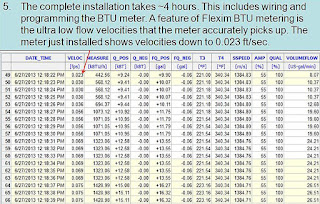
Installation of the BTU meter.
Typically takes about 4 hrs.

HVAC (Heating, Ventilation, Air Conditioning) primarily is an endeavor that generates and moves
thermal energy throughout an enclosed space. Commercially available technology now allows a building operator to accurately measure that movement of thermal energy throughout a system or building. The process is generally called BTU metering and has a number of justifiable benefits.
  • Real time equipment performance measurement.
  • Sub metering can indicate specific areas of consumption.
  • Ability to directly bill multiple tenants in a single building for their thermal energy usage.
  • Monitor and balance energy flows.
BTU metering essentially involves inlet and outlet temperature measurement of heat transfer liquids, along with their flow rate. While the principle is simple, the intricacies of the measurement methods and equipment accuracy can have a substantial impact on the accuracy, and thus the benefit, of the measurement data. Additionally, adding more instrumentation to an already complex system can create an additional on-going maintenance and calibration burden to retain the necessary levels of accuracy and function. Success at gaining the benefit of the performance data while minimizing the additional maintenance burden due to the instrumentation should be the goal.

MS Jacobs BTU Metering
Click for larger image.
One solution calls for the use of clamp on ultrasonic flow meters to measure liquid flow, coupled with temperature measurement in a single unit that will perform necessary calculations and provide output data in useful engineering units. An overarching benefit of the clamp on meter is its non-invasive nature, allowing its retrofit to in-place systems with no disturbance to existing piping. Here are some other characteristics of a highly effective BTU measurement unit:

  • No wear mechanism as part of the flow measurement unit
  • Traceable accuracy of flow and temperature measurements
  • Simple installation in new or retrofit applications without disruption to system operation
  • Reliable and maintenance free operation
  • Accurate measurement from near zero flow rate to maximum system flow
  • Stable sensing with no zero drift
  • Communications protocol to match building energy management system
  • Large storage cache for data, in case of communication failure
  • Common output signals, 4-20 ma or other, usable with selected ancillary equipment

Selecting the right equipment or instrumentation is the most important step along the path of adding measurement capability to increase efficiency. Without a solid stream of reliable data, useful decisions become difficult. Contact a product application specialist and share your goals and challenges. Leverage your own knowledge and experience with their product application expertise to develop an effective solution.

M.S. Jacobs & Associates

M.S. Jacobs & Associates is a leading manufacturer's representative and distributor of industrial instrumentation and controls in Western Pennsylvania, West Virginia and New York. MS Jacobs services and supplies products in all major industrial markets, including power generation, chemical processing, pulp and paper, oil and gas production, water and wastewater treatment, and nuclear power generation.

https://msjacobs.com
800-348-0089

Load Cells in Process Measurement

industrial process measurement load cells
Low profile low cells applied for tank and vessel
weighing and level indication.
Image courtesy Minebea Intec
In industrial application of process measurement and control, principles of the physical sciences are combined with technology and engineering to create devices essential to modern high speed, high accuracy system operation.

Load cells are the key components applied to weighing materials in modern processing. Load cells are utilized throughout many industries in process weighing operations. In application, a load cell can be adapted for measurement of items from the very small to the very large.

In essence, a load cell is a measurement tool which functions as a transducer, predictably converting force into a unit of measurable electrical output. While many types of load cells are available, the most popular cell in multiple industries is a strain gauge based cell. These strain gauge cells typically function with an accuracy range between 0.03% and 0.25%. Pneumatically based load cells are ideal for situations requiring intrinsic safety and optimal hygiene and, for locations without a power grid, there are even hydraulic load cells, which function without need for a power supply. These different types of load cells follow the same principle of operation: a force acts upon the cell (typically the weight of material or an object) which is then returned as a value. Processing the value yields an indication of weight in engineering units. For strain gauge cells, the principle of deformation applies, where extremely small amounts of deformation, directly related to the stress or strain being applied to the cell, are output as an electrical signal with value proportional to the load applied to the cell. The operating principle allows for development of devices delivering accurate, precise measurements of a wide range of industrial products. Advantages of load cells include their longevity, accuracy, and adaptability to many applications, all of which contribute to their usefulness in so many industries and applications.

Share your process weighing challenges with product application specialists. Leverage your own knowledge and experience with their product application expertise to develop an effective solution.

Closed Loop Electronic Pressure Controller

electronic pressure controller
Electronic pressure controller provides closed loop PID
control of outlet pressure.
Image courtesy of Rotork Instruments - Fairchild
The control of pressure in a line, tank or other vessel is a common operation found in the process control field. Many pressure regulators are fully mechanical, with counterforce mechanisms used to set an equilibrium point for the regulator. While these devices are effective, they lack the level of functionality available in an electronically controlled device.

Rotork Instruments, as part of their Fairchild brand, offers a series of electro-pneumatic pressure controllers that have built in PID closed loop microprocessor control utilizing a remote analog or digital setpoint signal. The electronic controller regulates feed and bleed solenoid valves to control pressure in the signal chamber of the booster section. Outlet pressure is measured and used as a feedback signal to the controller to provide accurate control of the outlet pressure. The device functions as a volume booster and I/P transducer.

Any of the devices can be controlled from the onboard keypad or a remote signal. A remote pressure sensor line can also be used with the controller to derive the feedback signal from further downstream from the instrument. This is helpful in eliminating pressure drop effects over the distance from the controller to an identified process point. The remote sensing also can improve system response. Adding the remote sensing is simple, just remove the factory installed plug and install an adapter that facilitates a line connection.

The various models are available with volume booster sections rated for 1 to 700 SCFM. More detail is found in the specification sheet provided below. Share your pressure control challenges with process measurement and control specialists. Leverage your own knowledge and experience into an effective solution with their product application expertise.


Duplex Basket Strainer

duplex basket strainer with changeover diverter valve
A duplex basket strainer allows continuous process flow
when strainer basket requires cleaning.
Image courtesy Fabrotech
Liquid processing systems of many types and application require protection from particulate matter in the flow path. Often, there are mechanical components that cannot tolerate particulate matter greater than some maximum diameter. Pumps, valves, sensors, and other specialties can experience accelerated wear and tear, even clogging, from particulate matter entrained within the liquid flow.

Once the maximum particulate diameter has been determined for various portions of the system, a plan can be implemented that provides a properly sized and configured device in place to remove particulates larger than the greatest allowable size. It is conceivable that identifiable parts of a system will have differeing protection requirements, resulting in the use of several or many different filtration elements throughout the system. Filtration units can range from very small inline filter units protecting a single instrument, to large centralized high flow rate units protecting extended portions of the system.

A basket strainer will be an appropriate choice for many applications. Coordination of strainer housing connection size and type, along with design flow rate and pressure drop are in order. The materials of construction for the housing, strainer basket and other wetted parts should be evaluated for suitability with the process media. A final consideration is the holding capacity of the strainer basket itself. Too small a strainer will lead to a service frequency for cleaning that can prove cumbersome for operating personnel.

Regardless of the type of strainer or filter used, a key consideration is whether the system can be temporarily shut down, or the filter bypassed, while replacement or cleaning of the filtration element is accomplished. A basket strainer, one of several types of liquid filtration devices, is available in both simplex and duplex variants. A simplex basket strainer functions as a single inline unit, requiring flow stoppage or bypass when the basket becomes clogged with debris. The changeover time may not be long, but some processes cannot tolerate any downtime. A duplex strainer is comprised of two simplex strainers incorporated into a common housing. An inlet chamber and diverting valve selects which strainer basket will process the liquid flow, while isolating the other. Changes in pressure drop through the device can be used to signal when it is time to switch operation between the strainer sections.

Fluid filtration is an important part of keeping a process in operation, reducing wear and tear on piping system components and equipment. Share your process fluid filtration challenges and requirements of all types with application specialists. Leverage your own process knowledge and experience with their product application expertise to develop an effective solution.

Installation Basics for Ball Valves

three piece industrial ball valve
Three piece industrial ball valve, manually operated
Image courtesy of Duravalve, Inc.
Ball valves are characterized by their closure mechanism. Most often, a ball valve has a spherically shaped fabrication (ball) that is inserted in the fluid flow path. The ball has an opening through its center, often circular in cross section and matching the diameter and shape of the connected pipe. The ball is contained within the body of the valve and rotated around its central axis by torque applied to the stem. The stem, which extends through a seal to the exterior of the valve body, can be manually or automatically controlled via several methods.

During valve operation, the ball is rotated through a ninety degree arc from a fully closed to fully open position. When fully closed, the opening in the ball faces the sidewalls of the valve body and is cut off from the fluid by seals that secure the ball in place and prevent fluid flow around the ball. As the valve stem is rotated toward the open position, the cross sectional area of the opening is increasingly exposed to the fluid flow path until the open area through the ball is aligned with the flow path in the fully open position.

Here are some general installation and removal guidelines for ball valves.

  • Verify whether the valve is unidirectional or bidirectional. If valve function is limited to a single direction, make sure the inlet and outlet ports are properly oriented to the piping system flow direction.
  • Adequate access for handle movement, along with an operator's hand, should be confirmed prior to installing the valve.
  • Ball valves will function in any orientation.
  • If automated with an actuator, maintain sufficient clearance around the valve and actuator to provide adequate maintenance access.
  • Keep the installation area free of debris and dirt. Protect any valve parts that are removed or are awaiting installation. Avoid introducing any foreign matter, dirt or debris into the valve.
  • Valves may have any of a number of connection methods, including threaded, flanged, or socket weld. Disassembly of the valve may be appropriate when installing some types, especially socket weld. Care should be taken to avoid any damage to the ball surface, seals, or sealing surfaces. Scratches and nicks can produce leakage when the valve is reassembled.
  • If disassembling a currently installed valve, verify that the piping system is not under pressure prior to starting. Cycle the valve through open and closed positions a couple times to relieve any pressure that may be retained in the valve body.
  • Follow all manufacturer recommendations for applied torque on any fasteners.
  • When a ball valve is disassembled, for any reason, it may be a good time to replace seats.
  • Leak check final installation. Tighten packing gland nut to eliminate leaks at the stem.
These are general recommendations. In every instance, a review of the valve manufacturer's specific instructions prior to starting installation or service is good practice. Share your fluid control challenges with industrial valve specialists. Leverage your own knowledge and experience with their product application expertise to develop effective solutions.