Load Cells in Process Measurement

industrial process measurement load cells
Low profile low cells applied for tank and vessel
weighing and level indication.
Image courtesy Minebea Intec
In industrial application of process measurement and control, principles of the physical sciences are combined with technology and engineering to create devices essential to modern high speed, high accuracy system operation.

Load cells are the key components applied to weighing materials in modern processing. Load cells are utilized throughout many industries in process weighing operations. In application, a load cell can be adapted for measurement of items from the very small to the very large.

In essence, a load cell is a measurement tool which functions as a transducer, predictably converting force into a unit of measurable electrical output. While many types of load cells are available, the most popular cell in multiple industries is a strain gauge based cell. These strain gauge cells typically function with an accuracy range between 0.03% and 0.25%. Pneumatically based load cells are ideal for situations requiring intrinsic safety and optimal hygiene and, for locations without a power grid, there are even hydraulic load cells, which function without need for a power supply. These different types of load cells follow the same principle of operation: a force acts upon the cell (typically the weight of material or an object) which is then returned as a value. Processing the value yields an indication of weight in engineering units. For strain gauge cells, the principle of deformation applies, where extremely small amounts of deformation, directly related to the stress or strain being applied to the cell, are output as an electrical signal with value proportional to the load applied to the cell. The operating principle allows for development of devices delivering accurate, precise measurements of a wide range of industrial products. Advantages of load cells include their longevity, accuracy, and adaptability to many applications, all of which contribute to their usefulness in so many industries and applications.

Share your process weighing challenges with product application specialists. Leverage your own knowledge and experience with their product application expertise to develop an effective solution.

Closed Loop Electronic Pressure Controller

electronic pressure controller
Electronic pressure controller provides closed loop PID
control of outlet pressure.
Image courtesy of Rotork Instruments - Fairchild
The control of pressure in a line, tank or other vessel is a common operation found in the process control field. Many pressure regulators are fully mechanical, with counterforce mechanisms used to set an equilibrium point for the regulator. While these devices are effective, they lack the level of functionality available in an electronically controlled device.

Rotork Instruments, as part of their Fairchild brand, offers a series of electro-pneumatic pressure controllers that have built in PID closed loop microprocessor control utilizing a remote analog or digital setpoint signal. The electronic controller regulates feed and bleed solenoid valves to control pressure in the signal chamber of the booster section. Outlet pressure is measured and used as a feedback signal to the controller to provide accurate control of the outlet pressure. The device functions as a volume booster and I/P transducer.

Any of the devices can be controlled from the onboard keypad or a remote signal. A remote pressure sensor line can also be used with the controller to derive the feedback signal from further downstream from the instrument. This is helpful in eliminating pressure drop effects over the distance from the controller to an identified process point. The remote sensing also can improve system response. Adding the remote sensing is simple, just remove the factory installed plug and install an adapter that facilitates a line connection.

The various models are available with volume booster sections rated for 1 to 700 SCFM. More detail is found in the specification sheet provided below. Share your pressure control challenges with process measurement and control specialists. Leverage your own knowledge and experience into an effective solution with their product application expertise.


Duplex Basket Strainer

duplex basket strainer with changeover diverter valve
A duplex basket strainer allows continuous process flow
when strainer basket requires cleaning.
Image courtesy Fabrotech
Liquid processing systems of many types and application require protection from particulate matter in the flow path. Often, there are mechanical components that cannot tolerate particulate matter greater than some maximum diameter. Pumps, valves, sensors, and other specialties can experience accelerated wear and tear, even clogging, from particulate matter entrained within the liquid flow.

Once the maximum particulate diameter has been determined for various portions of the system, a plan can be implemented that provides a properly sized and configured device in place to remove particulates larger than the greatest allowable size. It is conceivable that identifiable parts of a system will have differeing protection requirements, resulting in the use of several or many different filtration elements throughout the system. Filtration units can range from very small inline filter units protecting a single instrument, to large centralized high flow rate units protecting extended portions of the system.

A basket strainer will be an appropriate choice for many applications. Coordination of strainer housing connection size and type, along with design flow rate and pressure drop are in order. The materials of construction for the housing, strainer basket and other wetted parts should be evaluated for suitability with the process media. A final consideration is the holding capacity of the strainer basket itself. Too small a strainer will lead to a service frequency for cleaning that can prove cumbersome for operating personnel.

Regardless of the type of strainer or filter used, a key consideration is whether the system can be temporarily shut down, or the filter bypassed, while replacement or cleaning of the filtration element is accomplished. A basket strainer, one of several types of liquid filtration devices, is available in both simplex and duplex variants. A simplex basket strainer functions as a single inline unit, requiring flow stoppage or bypass when the basket becomes clogged with debris. The changeover time may not be long, but some processes cannot tolerate any downtime. A duplex strainer is comprised of two simplex strainers incorporated into a common housing. An inlet chamber and diverting valve selects which strainer basket will process the liquid flow, while isolating the other. Changes in pressure drop through the device can be used to signal when it is time to switch operation between the strainer sections.

Fluid filtration is an important part of keeping a process in operation, reducing wear and tear on piping system components and equipment. Share your process fluid filtration challenges and requirements of all types with application specialists. Leverage your own process knowledge and experience with their product application expertise to develop an effective solution.

Installation Basics for Ball Valves

three piece industrial ball valve
Three piece industrial ball valve, manually operated
Image courtesy of Duravalve, Inc.
Ball valves are characterized by their closure mechanism. Most often, a ball valve has a spherically shaped fabrication (ball) that is inserted in the fluid flow path. The ball has an opening through its center, often circular in cross section and matching the diameter and shape of the connected pipe. The ball is contained within the body of the valve and rotated around its central axis by torque applied to the stem. The stem, which extends through a seal to the exterior of the valve body, can be manually or automatically controlled via several methods.

During valve operation, the ball is rotated through a ninety degree arc from a fully closed to fully open position. When fully closed, the opening in the ball faces the sidewalls of the valve body and is cut off from the fluid by seals that secure the ball in place and prevent fluid flow around the ball. As the valve stem is rotated toward the open position, the cross sectional area of the opening is increasingly exposed to the fluid flow path until the open area through the ball is aligned with the flow path in the fully open position.

Here are some general installation and removal guidelines for ball valves.

  • Verify whether the valve is unidirectional or bidirectional. If valve function is limited to a single direction, make sure the inlet and outlet ports are properly oriented to the piping system flow direction.
  • Adequate access for handle movement, along with an operator's hand, should be confirmed prior to installing the valve.
  • Ball valves will function in any orientation.
  • If automated with an actuator, maintain sufficient clearance around the valve and actuator to provide adequate maintenance access.
  • Keep the installation area free of debris and dirt. Protect any valve parts that are removed or are awaiting installation. Avoid introducing any foreign matter, dirt or debris into the valve.
  • Valves may have any of a number of connection methods, including threaded, flanged, or socket weld. Disassembly of the valve may be appropriate when installing some types, especially socket weld. Care should be taken to avoid any damage to the ball surface, seals, or sealing surfaces. Scratches and nicks can produce leakage when the valve is reassembled.
  • If disassembling a currently installed valve, verify that the piping system is not under pressure prior to starting. Cycle the valve through open and closed positions a couple times to relieve any pressure that may be retained in the valve body.
  • Follow all manufacturer recommendations for applied torque on any fasteners.
  • When a ball valve is disassembled, for any reason, it may be a good time to replace seats.
  • Leak check final installation. Tighten packing gland nut to eliminate leaks at the stem.
These are general recommendations. In every instance, a review of the valve manufacturer's specific instructions prior to starting installation or service is good practice. Share your fluid control challenges with industrial valve specialists. Leverage your own knowledge and experience with their product application expertise to develop effective solutions.

High Density Signal Conditioners

microblox signal conditioning module
MicroBlox™ signal conditioning modules offer broad
functionality in a very compact package.
Image courtesy Acromag
Signal conditioning is a common function needed for proper operation of data acquisition or process control systems. The general purpose of signal conditioning is to convert an input signal of one type to an output signal of another, completing a usable path of information from signal generating device to signal using device. With many control and data acquisition systems employing numerous input signals from diverse sources and instruments, a control panel benefits from having a consolidated, adaptable means of performing all the required signal conditioning while occupying a minimized footprint in the panel.

The microBlox™ line of signal conditioners, from Acromag, provides a broad range of signal conditioning functionality in a compact and rugged industrial package. The microBlox™ line of signal conditioners provides a wide array of useful features, broad range of I/O signal compatibility, and a very compact high density footprint. The input modules offer screwless mounting in a choice of backplanes accommodating up to 16 channels. Functions included transmitter, alarm, and signal conditioner.

The variety of available models, some with economical precalibrated ranges, is extensive. The module construction, with its overmolded circuitry, provides resistance to dust, moisture, vibration and shock. The most valued capability of microBlox™ input modules is their Bluetooth connectivity. Mobile devices running either the Android or Apple versions of the Agility app can communicate with enabled modules to perform setup and configuration, diagnostic and troubleshooting functions. Input polling and trending is also possible using the app.

More technical data, illustration and description of the microBlox™ signal conditioners is included below. Share your signal conditioning and I/O challenges with a a product specialist. Leverage your own process knowledge and experience with their product application expertise to develop effective solutions.


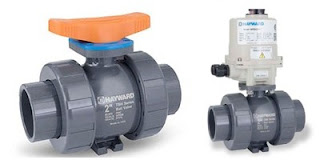
Thermoplastic Industrial Ball Valves

thermoplastic floating ball valves for industrial use
Thermoplastic ball valves, TBH Series.
Image courtesy Hayward Flow Control
Ball valves are a mainstay of fluid control
throughout many industries. Like most valve types, the ball valve is named for its closure mechanism. A spherical shaped element is placed in the fluid flow path, with the ability to rotate its position around an axis. The axis is a shaft or other device that connects to an actuator on the exterior of the valve. The actuator can be a simple handle or an element of a valve automation system. The “ball” in the ball valve has an opening through its center, usually round to mimic the shape of the connected pipe. As the ball is rotated, the opening aligns with the inlet and outlet of the valve body, allowing fluid to pass. A counter-rotation that aligns the port (opening) with the sides of the valve body, away from the flow path, stops the fluid flow. A seat between the exterior surface of the ball and the containing valve body prevents fluid from flowing around the ball.

The basic ball valve design centers around either a floating ball or trunnion mounted ball. A floating ball valve uses the body and the seats to hold the ball in place, with the connecting shaft serving primarily as the rotating mechanism. This design can provide bidirectional closure, since the fluid flow seats the ball against one of the sealing surfaces. A trunnion mounted ball valve has positioning support pins that mate with machined portions of the valve body to hold the ball in place and serve as the axis of rotation. Trunnion valves are available in sizes larger than those of the floating ball design.

Various common and exotic metals are routinely used for body and internal construction. Thermoplastic ball valves are an alternative that provides high levels of corrosion resistance to the media, as well as the surrounding environment.

Typical applications for thermoplastic ball valves:

  • Municipal waste and water treatment
  • Clean water technology
  • Chemical transfer and processing
  • Aquatic and animal life support systems
  • Mining and mineral processing
  • Metal plating
  • Marine
  • Pulp and paper
  • Landfills and environmental infrastructure
Some detailed information about thermoplastic ball valves from Hayward Flow Control is provided below. There are more variants to fulfill a wide band of applications. Share your fluid control challenges with a process control specialist and leverage your own knowledge and experience with their product application expertise to develop an effective solution.


Pre-Assembled Self-Regulating Heating Cable Solves a Range of Freeze Protection Challenges Quickly

self regulating heat cable with termination
Preconfigured and terminated heat cable, self regulating,
can speed project completion.
Image courtesy BriskHeat Corp.
Heat tracing a pipe, from start to finish can be time consuming. Selecting the various components, starting with the heating cable itself, extends through termination kits, controllers, mounting hardware and other electrical hardware needed to put the heating system in operation. BriskHeat has a product that, for many applications, offers a very simple and quick solution.

Pre-assembled self regulating heat cable is available in two voltage ranges, two watt densities, and prefabricated lengths up to 150 feet. Each cable is terminated at each end, saving the installer time. The cable is flexible enough for a spiral installation or to wrap around valves in the piping system. The self regulating aspect of the cable negates the need for a controller and power switching devices. Assemblies targeted for 120 volt applications are provided with a factory installed plug. The 208-277 volt cables will arrive with bare wire leads for installation of a customer provided connector. The cable can be easily installed using fiberglass or aluminum tape. Suitable insulation applied over the finished work will improve the performance of the heating system.

Share your heat trace and freeze protection challenges with industrial heating specialists, leveraging your own knowledge and experience with their product application expertise.