White Paper - Industrial Control System Cybersecurity Primer

industrial control system cyber security
Industrial control system cybersecurity is a global issue
The International Society of Automation is offering a free white paper entitled “What Executives Need to Know About Industrial Control Systems Cybersecurity”. The article provides useful commentary and information that establishes the scope of cybersecurity in the industrial process control space and provides a basic framework for understanding how every process may be impacted by lax cybersecurity efforts. The author, Joseph Weiss, differentiates Industrial Control System (ICS) cybersecurity from that of organizational IT through a review of various attributes common to both types, including message confidentiality, integrity, time criticality, and more. Any reader’s awareness and understanding of the cybersecurity risks to their operation will be enhanced through this article. I finished reading the article wanting more on the subject, and ISA is certainly a resource for additional content.

A quote from the article...
“Cyber incidents have been defined by the US National Institute of Standards and Technology (NIST) as occurrences that jeopardize the confidentiality, integrity, or availability (CIA) of an information system.”
ICS cybersecurity extends beyond preventing malicious outside intruders from gaining access. It is an important part of maintaining the overall operating integrity of industrial processes. A holistic approach is advocated to identify physical risk factors to the process and its componentry (post on device protection), as well as vulnerabilities that may prevent exploitation by unauthorized parties. Weiss goes on to describe the role and qualifications of the ICS Cybersecurity Expert, essentially an individual that can function effectively as an IT cybersecurity tech with the added skills of an industrial control systems expert.

A synopsis of attack events is provided in the article, with the author’s conclusion that not enough is being done to secure industrial control systems and the risk exposure is substantial in terms of potential threats to personnel, environment, and economy. By providing your name and email address, you can obtain the white paper from the ISA website. Your time spent obtaining and reading the article will be well spent.

For any specific information or recommendations regarding our products and cybersecurity, do not hesitate to contact us directly. We welcome any opportunity to help our customers meet their process control challenges.

Analynk Wireless Overview Video - Wireless Connectivity For Process Measurement and Control


M.S. Jacobs handles the Analynk line of industrial wireless  products. Available for use in almost every industrial environment, including those rated hazardous, Analynk products enable extension of your industrial WiFi into hazardous areas. Other products enable radio links between process measurement and control locations on a local, remote, or global scale. The video provides a summation of the company's product offering.

Share your wireless connectivity challenges with product application specialists and work together to develop effective connectivity solutions.

Thermoelectric Generator for Remote Site Power Generation

thermoelectric generators remote power system
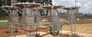
Thermoelectric generators at remote site
Courtesy Gentherm GPT
Some operations, by their nature, dictate the location in which they will be undertaken. An obvious example is oil and gas production, but there are many others. These sometimes challenging locations burden designers and operators with providing remote communications, even on site power generation. Remote installations can often be unattended, yet require reliable continuous electric power to operate. Establishing an on site power source requires thoughtful selection of technology and equipment to provide the best solution.

thermoelectric generator is one of several solutions to consider as a power source at a remote location. Each generation technology has a set of attributes making it more or less desirable for an application under consideration.

Thermoelectric generators convert heat directly into electricity using a fuel source for heat, a hermetically sealed thermopile, cooling fins, and no moving parts. The TEG delivers a low maintenance and cost effective solution for remote power requirements, having operational and cost benefits over engine driven generators, batteries and solar sources for many applications.

The short document below provides an overview of thermoelectric generator operation and application. Talk to a product specialist about your need to power and communicate with a remote site. A thermoelectric generator may be an option you had not considered, but may prove to be the best solution.


Installing a Clamp-on Ultrasonic Flow Meter

industrial process ultrasonic flowmeter clamp on style
Ultrasonic flow meter with clamp on sensor
Courtesy Flexim
Ultrasonic flow meters are utilized throughout the fluid processing industries, as well as for compressed air and energy monitoring. The non-invasive nature of the sensor installation couples with sufficient accuracy and low maintenance requirements to give this technology a competitive edge for many applications.

Producing consistently accurate results with an ultrasonic flow meter depends heavily on a proper installation. Flexim, a globally recognized leader in the manufacture of ultrasonic flow meters, provides us with a video that steps through the installation process, with recommendations and guidance along the way.

Flexim manufactures a full range of ultrasonic flow measurement equipment and instruments for industrial and commercial applications. Share your flow measurement challenges with process measurement experts, combining your process knowledge with their product application expertise to develop effective solutions.

Monitoring Generator Sets in Standby Mode Increases Reliability

Remote Monitoring of Electric Generator in Standy Mode
Electrtic generators used as backup power sources play a critical role in maintaining operations at many facilities. They may be automatically test run periodically, but still sit idle for extended times. Continuous remote monitoring of equipment condition can reduce the risk of a failed start.

Acromag, a globally recognized manufacturer of signal conditioning equipment, has authored an application note outlining the extent of remote monitoring that should be employed and how to accomplish it.

The application note is included below. Share your process signal conditioning and transmitting challenges with product specialists, combining your process knowledge with their product application expertise to develop effective solutions.


In-Line Thermal Flow Meters

in-line thermal dispersion flow meters
In-line thermal dispersion flow meters
Thermal Instrument Company
Thermal dispersion mass flow meters provide an accurate means of mass flow measurement with no moving parts and little or no encroachment on the media flow path. There are a number of different configurations to be found among various manufacturers, but all function in basically the same manner.

Two sensors are exposed to the heat transferring effect of the flowing media. When the media composition is known, the mass flow can be calculated using the meter reading and the pipe cross sectional area. One of the flow meter sensors is heated, the other is allowed to follow the media temperature as a reference. The heat dispersion from the heated sensor is measured and used to calculate mass flow.

Some positive attributes of thermal dispersion flow meters:

  • In-line and insertion configurations available to accommodate very small to large pipe sizes
  • Rugged Construction – Stainless Steel with available protective coatings and other specialty metals
  • No moving parts
  • Measure liquid or gas in general, sanitary, and ultra pure applications
  • Measurement not adversely impacted by changes in pressure or temperature
  • Wide range of process connections 
  • In-line versions provide unobstructed flow path
  • Wide turndown suitable for extended flow range
  • Back up sensors for extended life
  • Sensors do not contact process media
  • Flow and total flow measured
  • 4-20 mA output interfaces easily with other instruments and equipment
Share all your process measurement challenges and requirements with product application specialists, combining your process knowledge with their product application expertise to develop effective solutions.

Foot Valves: Basic, Hidden, Essential

industrial valve foot valve suction valve
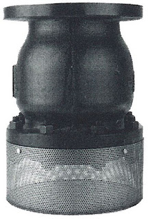
Foot valve showing inlet filter screen
Colton Industries
A foot valve is a purpose specific check valve. Designed for immersion in a well, tank, or other liquid containing vessel, it serves as a one-way inlet valve on piping leading to the suction side of a pump. Foot valves and their connected piping will extend downward from the pump suction elevation. The purpose of the valve is to maintain prime on the pump by preventing the water column in the suction line from collapsing, due to gravity, and draining all the liquid from the suction side of the pump system.

For industrial applications, there are numerous versions of foot valves available in varying sizes, capacities and materials of construction. The function of the valve is simple, so the key selection criteria can be focused on features that will contribute to longevity and reduce or eliminate any maintenance burden.

The data sheet below provides some good illustrations of a foot valve and how it is installed. Share your fluid processing and control challenges with application experts, combining your process and facility knowledge with their product application expertise to develop effective solutions.

Pneumatic Volume Booster Function

pneumatic volume booster
Pneumatic Volume Booster
Fairchild
A volume booster is used in a pneumatic control system to relay a low flow signal as one with greater flow volume. The common configuration is to provide a 1:1 ratio between the input and output pressure, keeping the input and output signals the same pressure. Products are available that deliver different ratios.

The general purpose of a volume booster is to provide a relay between a system with low flow volume and one with higher volume requirements. A typical example is a pneumatic actuator. The flow available through the pneumatic signal line may be insufficient to deliver the response rate desired from the pneumatic actuator. A volume booster, with control over an independent air supply, solves this challenge with increased flow volume at the same pressure as the control signal.

Volume boosters are simple in operation. The input signal applies force to one side of a diaphragm, the output pressure to the other. An imbalance between the two applied pressures will cause the diaphragm to move, changing the position of the valve and the outlet pressure until the two forces are again in balance. Little maintenance is required when the units are properly installed and supply air is of good quality.

The unit pictured is from Fairchild, a well recognized manufacturer of industrial pneumatic components, and provides a 1:1 ratio. There are some key points in the selection process, so reach out to a product specialist with your pneumatic system challenges and requirements. Combining your process and facility knowledge with their product application expertise will produce effective solutions.


Conductivity Controller For Boiler Applications

Multivariable water quality controller
Conductivity controller for boiler applications
Lakewood Instruments
Modern boilers using the Rankine cycle require feedwater and make-up feedwater quality maintained within certain limits with respect to alkalinity, conductivity, and other factors in order to maintain boiler operating efficiency and minimize maintenance requirements.

Controlling the feedwater quality can be accomplished with the addition of controlled amounts of the right chemicals to regulate various aspects of water quality. Another method is to purge, or blowdown, the boiler in a measured fashion that allows fresh feedwater to replace overly contaminated water. Filtration, which I generally deem to include ion exchange, reverse osmosis, and mechanical filtration, is a third method. All deal specifically with a limited scope of contaminates that have an impact on boiler operation and longevity.

Boiler blowdown can be used to limit the amount of total dissolved solids in the boiler drum water. As water boils, the dissolved solids in the water concentrate in the remaining liquid water. Blowdown purges a portion (or all) of this water, allowing the addition of water, presumably treated, with substantially lower total dissolved solids.

Boiler blowdown has an energy cost, since the replacement water must be heated to the design condition. It follows that executing this procedure should be undertaken when necessary, but not more frequently. A conductivity monitor and controller can accomplish properly timed blowdown cycles. The system consists of a conductivity sensor and a control unit that provides all the necessary functionality in a single integrated package. A data sheet is included below for one such unit from Lakewood Instruments.

Share your boiler operation challenges with an instrumentation specialist an explore how a properly instrumented steam system can provide operational savings and extended time between failure.


Process Control - Annunciator Panel as Cyber Defense Measure

Process control annunciator panel
Standalone Annunciator Panel
Ronan Engineering Company
There are numerous applications for annunciator panels, stations, and equipment throughout the various industrial markets. One such application, arising and growing with the connectivity of industrial control systems to the internet, is in the cyber defense arena.

Industrial control systems are increasingly internet connected, making them vulnerable to cyber attack. There was a time when all that was necessary for plant or operation security was installing a perimeter fence around the property and posting a guard at the gate. Our industrial control systems are now subject to mischief or malicious attack from locations and parties unknowable and worldwide.

Do you know of ICS-CERT? If involved in industrial control, you should. It is the Industrial Control Systems Cyber Emergency Response Team, a part of the Department of Homeland Security that provides operational capabilities to defend control systems against cyber threats. You can follow them on Twitter, @ICS-CERT, and monitor the vulnerabilities and threats that they discover in the industrial control sphere. New items are added almost daily, naming specific vulnerabilities uncovered in named systems and equipment. Chances are that you will discover some of the equipment in your plant listed.

Annunicator systems and equipment can be employed as an isolated "watcher", monitoring process performance and providing alerts when conditions exceed specified limits.
A major impact of a potential cyber attack scenario is that, as operator, you can no longer fully trust what your software based internet connected control system is telling you, or whether it is doing everything it should and only those things that it should. An annunciator system, isolated from the primary control system and the internet, monitoring critical process conditions, incorporates a substantial level of safety against cyber attack.

There is more to be learned. Browse the document included below for a detailed visual demonstrating the set up of annunciators that can be isolated from your network. Share your process control challenges with specialists, and combine your process and facility knowledge with their product application expertise to develop effective solutions. And start following @ICS-CERT on Twitter and build your awareness and knowledge of industrial control cyber threats. 

Silicone Rubber Heater Blankets - Flexible Heat Where You Need It

silicone rubber flexible heating blanket
Silicone rubber heater in one
of its simplest forms
BriskHeat
Electric heaters for industrial and commercial applications are available in an almost dizzying range of types, materials, and forms. One of those is the silicone rubber heater.

Stock shapes and sizes are available from many manufacturers, but one distinct advantage of silicone rubber heaters is their flexibility. The resistance heater wires are encased in a silicone rubber sheet, providing the ability to wrap the assembly around an object or manipulate it into a close fit with the target of a heating application. The silicone rubber encasement also provides a high level of protection for the heater wires from impact, moisture, and some chemicals.

The watt density of the heaters can be specified to provide a good match between the delivery of heat and the need for it. Custom shapes and configurations can be manufactured to order, and on board or remote controllers provided. Pressure sensitive adhesive is a common option that facilitates the installation of the heater assembly to a part or vessel.

The maximum application temperature is in the range of +450°F (+232°). These heaters are a useful selection option for a large range of operations demanding heat to be applied directly to a surface, object, tank, drum, or other vessel. Share your industrial heating requirements with product specialists for the best match up between heater technology and your application.


Applying Precision Turbine Flow Meters

turbine flow meters flanged and threaded
High precision turbine flow meters
Courtesy Cameron Measurement Systems
Precision turbine flow meters are specially designed to accommodate a broad range of precise fluid measurement applications. They accommodate greater flow rates with lower pressure drops than other meters in their class. Some have a self-flushing design for longer sustained accuracy. The turbine's high-frequency digital output is suitable for interfacing with an assortment of readout and recording equipment. Some turbine flow meters have a symmetrical bi-directional design that supports reverse flow applications without a reduction in accuracy or capacity.

Operating Principle

(The following is excerpted from Model 700 Series Turbine Flowmeter User Manual, from Cameron Measurement Systems....with some editing)

Fluid flows over a diffuser section and is accelerated onto a multi-blade hydro-dynamically balanced turbine rotor. The rotor speed is proportional to the volumetric flow rate. As the rotor turns, a reluctance type pickup coil (mounted on the meter) senses the passage of each blade tip and generates a sine wave output with a frequency that is directly proportional to the flow rate.

The rotor is the only moving part of the turbine flow meter. The small lightweight rotor hubs ensure fast response to process flow changes. The rotor is hydro-dynamically balanced during operation, eliminating the need for mechanical thrust leveling. This low-friction design improves metering linearity and reduces wear and maintenance.

A variable reluctance generating pickup coil contains a permanent magnet and a wire winding. In some cases, the rotor blade of the turbine meter is made of a ferritic stainless steel such as grade 430. The movement of the rotor blade in proximity to the magnetic field of the coil tip produces an AC type voltage pulse within the coil winding. An alternate arrangement finds the ferritic bars embedded in the rotor shroud, where they can interact with the pickup coil. Increasing the quantity of bars on the shroud to outnumber the rotor blades provides more pulses per unit volume (resolution). This feature can be valuable when proving large-capacity meters with a small-volume prover. Shielded wire cable conveys the output of the pickup coil to compatible electronic instruments to indicate flow rate, record, and/or totalize the volumetric flow. The coil itself does not require electrical power to operate.

The meter may be factory-fitted with multiple coils for redundancy, indication of flow direction or pulse train verification. The pickup coil type and magnetic strength vary with application requirements.

The turbine flow meters are calibrated in a horizontal position. Therefore, the best correlation of calibration occurs when the meter is operated in this plane. However, the meter will operate satisfactorily in any position.

System Pressure

The maximum and minimum system pressures must be considered when applying the turbine meter. To obtain proper response, a back pressure should be applied to the meter. This back pressure should be at least twice the pressure drop of the meter at maximum flow. For liquid meters, the back pressure should be twice the pressure drop of the meter at maximum flow, plus twice the fluid vapor pressure.

Summary

Turbine flow meters, with their simple, durable construction and wide operating range, may be the right choice for a number of applications. As with all instrumentation, there are a number of factors to consider when making a selection. Share your flow measurement challenges and requirements with instrumentation specialists, combining your process knowledge with their product application expertise to develop the most effective solutions.

Video Demonstration of Transit Time Difference Method of Flow Measurement

portable ultrasonic flow meter Flexim
Portable Ultrasonic Flow Meter
Flexim
The measure of flow is a pervasive task in fluid process control. There are several differing technologies employed for measuring fluid flow, each with its own set of performance and application attributes that might make it the advantageous choice for a particular operation.

Ultrasonic flow measurement uses several methods for determining the average velocity of a fluid. One of those methods employs the difference in the transit times of ultrasonic pulses travelling with the flow direction and against the flow direction. The flow velocity of the media will offset the transit times between the flow and counterflow measurements. The measured difference in transit times can be used to determine average flow velocity and, with additional processing, mass flow.

Ultrasonic flow meters are accurate and provide repeatable results, making them suitable for custody transfer operations, as well as many other process control applications. Little maintenance is required and the units have no moving parts. Measurement instruments are available with in-line or clamp-on mounting, providing a high level of installation and application flexibility.

The short video below provides a clear explanation of how transit time difference measurement works. Share your flow measurement challenges and requirements with a product application expert, combining your process knowledge with their product expertise to develop effective solutions.


RTD or Thermocouple for Your Temperature Measurement Application?

RTD or thermocouple temperature sensor assembly
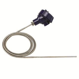
Temperature Sensor Assembly
Wika
Proper temperature sensor selection is key to getting useful and accurate data for maintaining control of a process. There are two main types of temperature sensors employed for industrial applications, thermocouple and resistance temperature detector (RTD). Each has its own set of features that might make it an advantageous choice for a particular application.

Thermocouples consist of a junction formed with dissimilar conductors. The contact point of the conductors generates a small voltage that is related to the temperature of the junction. There are a number of metals used for the conductors, with different combinations used to produce an array of temperature ranges and accuracy. A defining characteristic of thermocouples is the need to use extension wire of the same type as the junction wires, in order to assure proper function and accuracy.
Here are some generalized thermocouple characteristics.

  • Various conductor combinations can provide a wide range of operable temperatures (-200°C to +2300°C).
  • Sensor accuracy can deteriorate over time.
  • Sensors are comparatively less expensive than RTD.
  • Stability of sensor output is not as good as RTD.
  • Sensor response is fast due to low mass.
  • Assemblies are generally rugged and not prone to damage from vibration and moderate mechanical shock.
  • Sensor tip is the measuring point.
  • Reference junction is required for correct measurement.
  • No external power is required.
  • Matching extension wire is needed.
  • Sensor design allows for small diameter assemblies.
RTD sensors are comprised of very fine wire from a range of specialty types, coiled within a protective probe. Temperature measurement is accomplished by measuring the resistance in the coil. The resistance will correspond to a known temperature. Some generalized RTD attributes:
  • Sensor provides good measurement accuracy, superior to thermocouple.
  • Operating temperature range (-200° to +850°C) is less than that of thermocouple.
  • Sensor exhibits long term stability.
  • Response to process change can be slow.
  • Excitation current source is required for operation.
  • Copper extension wire can be used to connect sensor to instruments.
  • Sensors can exhibit a degree of self-heating error.
  • Resistance coil makes assemblies less rugged than thermocouples.
  • Cost is comparatively higher
Each industrial process control application will present its own set of challenges regarding vibration, temperature range, required response time, accuracy, and more. Share your process temperature measurement requirements and challenges with a process control instrumentation specialist, combining your process knowledge with their product application expertise to develop the most effective solution.


Installing Heat Tape - Instructional Video

BriskHeat manufactures a broad range of heating equipment and componentry. Their heat tape is routinely applied across many applications involving heating of gases, liquids, and solids. The video included below provides simple and well illustrated guidance for selecting and properly installing heat tape to provide for safety and longevity.

Heat tape is flexible in its application, inexpensive, and easy to use. The video shows the three basic types, along with their application limitations and basic selection criteria. Instruction is provided on how to properly prepare the installation surface. The tools and materials needed for installation are also shown.

Share your process, pipe, and valve heating challenges with application specialists. Combining your process or application knowledge with their product expertise will produce a good match between product and application.

BriskHeat Joins the M.S. Jacobs Lineup

industrial heaters
M.S. Jacobs is pleased to announce its new representation agreement with BriskHeat Corporation. The industrial heaters manufactured by BriskHeat complement many of the other quality products handled by M.S. Jacobs.

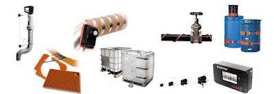
BriskHeat manufactures a broad line of heaters, insulators, and controls for almost every industrial application.

  • Cloth Heating Jackets and Insulators
  • Heating Tapes
  • Heating Cable
  • Laboratory Heaters and Equipment
  • Etched Foil Heaters
  • Silicone Rubber Heaters
  • Drum Heaters
  • Tote Tank / IBC Heaters
  • Gas Cylinder Warmers
  • Enclosure Heaters
  • Hopper Heating Systems
  • Personal Comfort Heating Solutions
  • Hazardous-Area Heaters
  • Plastic Bending Heaters
  • Resistance Wire
  • Temperature Controllers
  • Temperature Controllers for Outdoor Use
  • Insulators
  • Heaters and Controls with Canadian Approvals
  • Composite Curing Solutions
Share your industrial and process heating requirements with the product specialists at M.S. Jacobs & Associates. Combining your process expertise with their product knowledge will produce effective solutions.

Analynk Wireless For Process Control Connectivity


Analynk Wireless is an innovative designer and supplier of wireless instrumentation for the process control industry. Their instruments and equipment have been successfully implemented in numerous applications for temperature measurements, 4-20 mA bridges, discrete inputs/outputs, pulse inputs, lighting and pump controls. Analynk's products are used in both hazardous and non-hazardous locations. Watch the short video for a animated overview of Analynk products and capabilities.

Share your wireless connectivity challenges with product specialists. Combining your process knowledge with their expertise with produce effective solutions.

Gentherm GPT Provides Turnkey Remote Power

thermoelectric generators
Thermoelectric Generators, part of  a remote power system
There are many industrial operations and processes that operate outside the confines of a factory building. Some even operate outside the confines of what most consider "civilization". Sometimes, if you need electric power, you have to generate your own.

Gentherm Global Power Technologies specializes in providing equipment and complete systems to produce electric power at remote sites. Their signature product line is the thermoelectric generator, or TEG. It uses a solid state thermopile and gas fired heaters to generate DC current. The technology is especially useful at sites where gas is naturally present. As a turnkey systems provider, Gentherm GPT will design complete systems, customized and configured for each particular installation. Here is an example of a fuel gas conditioning system provided for an offshore oil rig, designed specifically to address an issue at the site.

GPT's power generation products are well suited for a wide array of applications.

  • Oil, gas, product, or water pipelines
  • Well sites
  • Offshore platforms
  • Telecommunication sites
  • Well monitoring and automation
  • Security and surveillance
  • Navigational aids
  • Communication systems
For your remote power generation projects, consider a thermoelectric generator. Contact a product specialist and share your requirements. Combining your project knowledge with their product expertise will produce an effective solution.


Don't Ignore the Simple Solution for Flow Measurement

flow indicator flow meter with fluid observation window
Flow indicator also permits visual
inspection of fluid
Courtesy ERDCO Engineering Corp.
For process control and commercial or industrial applications, there are numerous methods of flow measurement from which to choose. Technologies range from very simple applications of physical principles to deployment of very specialized electronics and sensors. The available range of accuracy, response, and cost is quite broad, with a general expectation that higher cost will deliver better performance and accuracy.

Making the best instrument selection for a flow measurement application should include an assessment of what the operators really need in order to safely and effectively run the process or perform the task related to the measurement of fluid flow. Installing instrumentation with capabilities far beyond what is required is almost certainly a waste of financial resources, but may also have an unexpected impact on operators. Through the generation of data that, while accurate, does not provide any actionable information about process condition, operators can be misled, similar to the occurrence of a false or nuisance alarm. Some applications call for high accuracy, some do not. Define your informational needs and select instruments that will meet those needs.

There is a large array of applications that can be satisfied with simpler, less costly measurement technology. These devices often employ turbines or vanes to produce an indication of flow rate. Incorporated into some of the instruments is a means to visually observe the flowing liquid to verify color and clarity. Simple devices sometimes are intended only to indicate the presence of fluid flow, and whether the flow rate is high or low. Configurations are available that allow insertion into lines under pressure (hot tap) through a full port ball valve. Other variants with combinations of features and capabilities abound.

The selection range is enormous, so define your minimum needs first, then search for a compatible product. Your search can be enhanced by contacting an instrumentation specialist. Combining your process expertise with their broad product knowledge will produce effective solutions.


Hayward Announces New Electric Valve Actuator Line

electric valve actuators with manual override
New HRS Series Electric Valve Actuators
Courtesy Hayward Flow Control
Hayward Flow Control issued a press release in early June announcing the introduction of its HRS Series of quarter turn electric valve actuators. The actuators complement the company's companion lines of fluid process products, including thermoplastic valves, strainers, filters, controls, bulkhead fittings and tank accessories, and corrosion resistant pumps.

The new HRS line provides practical features and benefits to users.
  • Product torque range from 300 in-lb to 177,000 in-lb
  • Aluminum housing with powder coat
  • Double square drive socket, ISO5211 compliant mounting
  • On/Off or Proportional Control  with 2-10 vdc or 4-20 ma inputs and outputs
  • NEMA 4/4X/IP67 enclosure rating
  • Range of available AC and DC voltages
  • Integrated local control station
  • Visual position indicators
  • CSA Certified, UL439
  • Two Year Warranty
There are numerous variants that can be configured using base models and available options. For more detail, contact a product specialist. Share your fluid process control challenges with them, combining your process knowledge with their product application expertise to produce the most effective solutions.


Tank Overfill Protection - Level Measurement Technology Resources for Best Results

crude oil storage tanks with overfill protection level measurement
Crude oil storage tanks, a beneficiary of overfill protection
Industrial liquid processing often includes tanks or other vessels for the storage or combining of product components, raw materials, or finished product. Regardless of the nature of the liquid, overfill and spillage are of concern due to economic loss, downtime, and the creation of hazardous conditions. Good practice calls for detection of overfill conditions in a reliable manner which will provide operators notice of the condition in time to avoid spillage.

Magnetrol®, a globally recognized leader in the field of liquid level measurement, has created a set of resources to help customers understand the need for overfill protection and properly establish a protocol. Different industries and products will have varying levels of risk or hazard, thus different governing standards. The basic benefit to overfill protection is the same throughout...whatever is in the tank should be contained. Included below is one of several resources provided by Magnetrol® to address the issue of overfill protection. You can get the entire set by contacting level control specialists.

There are a number of technologies employed in the measurement of liquid level. Each has its own set of attributes that may prove advantageous for a particular application. Share your level measurement and control challenges with a product application specialist. Combining your process expertise with their product application knowledge will produce effective solutions.


Level Measurement: Comparing Displacer Transmitters and Differential Pressure Transmitters

diagram of displacer level transmitter for process measurement and control
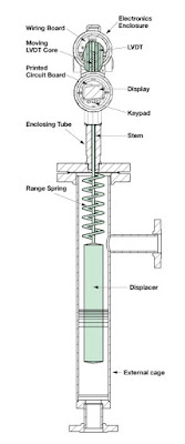
Electronic Displacer Transmitter
Courtesy Magnetrol
Liquid level measurement is ubiquitous throughout industrial fluid processing operations. Whether via direct or inferential means, the fluid level data point is an integral part of operational and safety plans for an installation.

Magnetrol, a globally recognized leader in the design and manufacture of level measurement instrumentation, has produced a comparison of displacer transmitters and differential pressure transmitters applied to liquid level measurement.

What is a displacer transmitter?


Displacer transmitters are considered a direct means of level measurement.

Quoted from Magnetrol website page on displacer transmitters...
Electronic displacer level transmitter technology operates by detecting changes in buoyancy force caused by liquid level change. These forces act upon the spring supported displacer causing vertical motion of the core within a linear variable differential transformer.
As the core position changes with liquid level, voltages are induced across the secondary windings of the LVDT. These signals are processed in the electronic circuitry and used to control the current in the 4-20 mA current loop. The enclosing tube acts as a static isolation barrier between the LVDT and the process media.

 How does a differential pressure transmitter measure liquid level?


Liquid level can be inferred through the measure of the pressure generated by the column of liquid in a tank or vessel. The measurement device must be calibrated for the specific gravity of the measured media in order to attain reasonably accurate results. There are a number of installation arrangements of differential pressure transmitters that will accommodate tanks open to atmosphere, closed pressurized tanks, and more.

The comparison is included below and provides some interesting points to consider. Share your level measurement application challenges with a product application specialist. Combining your process experience and knowledge with their product application expertise will produce the best solutions for your process measurement needs.


SVF Flow Controls Explains Surface Roughness for Valves Intended for Special Applications

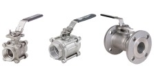
Socketed and flanged ball valves for industrial process control
Vales utillized in industrial processes
can require special materials or finishes.
Fluid control operations can sometimes require special materials of construction or finishes for piping and specialties, like valves. A segment of the industrial valve manufacturing sector specializes in providing fluid control valves with coatings, surface finish, and materials of construction suitable for the requirements of applications not well serviced by more common constructions.

One manufacturer, SVF Flow Controls, has published a short article explaining some of the basics about surface finish. The article defines surface finish and goes on to describe some of the methods employed to achieve various levels of surface roughness and texture. The article, included below in its entirety, is short and informative.

Share your specialty valve applications with product experts. The combination of your process expertise and their product knowledge will produce the most effective solutions.

High Density Signal Conditioning Modules Offer Bluetooth® Configuration of I/O Ranges and Alarms

Miniature high density signal conditioner module for process control I/O
The microBlox™ signal conditioners for high density I/O configuration
Acromag, a globally recognized manufacturer of signal conditioning modules and related equipment, announced a new product release earlier this month. The microBlox™ line of signal conditioners provides a wide array of useful features, broad range of I/O signal compatibility, and a very compact high density footprint.

Here is an excerpt from the Acromag newsletter from June 6, 2016.

A full line of microBlox™ isolated signal conditioning modules are now available from Acromag. Offering over 175 models, microBlox uB modules can safely interface a wide variety of voltage, current, temperature, frequency, and other field signals with a ±5V or 0-5V DC output to host measurement & control systems. Users can select modules with fixed ranges or wireless configuration via Bluetooth® wireless technology on an Android™ or iOS® mobile device. Acromag’s free AgilityTM app for smartphones and tablets simplifies setting custom I/O ranges and optional alarm functions. The app can also display input signal values and create sharable trend charts. uB modules snap securely into compact backpanels (no screws) in any mix with 4, 8 or 16-channel capacities. With 1500Vac peak (350Vdc continuous) channel-to-channel and field-to-host isolation, the hot-swappable modules are ideal to front-end data acquisition systems or Acromag remote I/O for communication to Ethernet, Modbus, or Profibus networks. High performance is assured with up to 0.05% accuracy and 130dB noise rejection. Prices start at just $90 per module.
 
“Advanced microcontroller and wireless technologies enable microBlox modules to bring greater flexibility and signal processing capabilities into such a small, economical package.” stated Robert Greenfield, Acromag’s marketing & sales director.
The microBlox module’s small size (1.11" x 1.65" x 0.4") and channel-by-channel scalability is ideal for embedded or portable applications such as test stands, defense systems, and process control applications. Well-suited for use in harsh industrial environments, the over-molded modules resist shock, dirt, and moisture with dependable operation from -40 to 85°C. Hazardous location UL/cUL Class 1 Div 2 and ATEX Zone 2 approvals are also available.
Accessories include a selection of backpanels with slots to insert 4, 8, or 16 modules. Fuse clips hold the modules securely without screws for easy insertion/removal. The backpanels support surface or DIN rail mounting and include CJC for use with temperature input modules. Blue LEDs indicate modules that are ready for Bluetooth wireless technology communication. Connections are provided for a 5V power source or a 10-32Vdc supply when used with the plug-in 5V power module. A DB25 header facilitates a single cable connection to interface all uB I/O signals directly to the host data acquisition system.
 A consolidated catalog describing the new microBlox™  signal conditioners is included below. Share your signal conditioning and I/O challenges with a a product specialist. Combining your process knowledge with their product application expertise will produce the best solutions.


MS Jacobs & Associates Offers Line of Corrosion Resistant Industrial Fluid Handling Process Control Equipment

corrosion resistant plastic industrial fluid handling flow meter
TKS/TKP/TKM Series PVC + PP Paddle Wheel Flow Meters
Courtesy Icon Process Controls Ltd.
MS Jacobs & Associates now represents ICON Process Controls in Pennsylvania, New York, and West Virginia. ICON specializes in corrosion resistant industrial fluid handling process control equipment, offering industry the most complete line of all plastic instrumentation products supported by the largest inventory in North America. Markets include Municipal and Industrial Water & Waste-Water Treatment, Bulk Chemicals, Steel Processing, Metal Finishing, Chemical Dosing Skids, and Food & Beverage.

The company's products complement and expand MS Jacobs' already extensive array of process measurement and control instruments and equipment. The ICON line includes devices for measuring and controlling flow, level, pressure, and temperature. Their unique all plastic construction makes the ICON equipment and instruments particularly well suited to the harshest industrial environments.

For information about the complete line of corrosion resistant industrial fluid handling process control equipment from ICON, reach out to the process control experts at MS Jacobs. Share you process control challenges and combine your process knowledge with their product application expertise to formulate the best solutions.
Building Steam System Efficiency for Profitable Returns

gas fired boilers in boiler room
Improvements in steam system efficiency can yield
substantial return on investment
Steam, an energy efficient, reliable, scalable form of transferring heat, is utilized throughout commercial, industrial, and institutional settings. The ubiquitous adoption and use of this heat transfer medium has resulted in steam generation ranking as a substantial line item on any organization's financial operating report. The scale of many steam production operations can produce some sizable payback opportunities from modifications that improve efficiency or reduce maintenance requirements.

The application of modern precision measurement instrumentation is one area where comparatively modest investments in system improvement can yield ongoing returns. Magnetrol International, a globally recognized leader in the design and manufacture of flow and level instrumentation, has produced a white paper describing aspects of the steam cycle that are candidates for profitable improvement and how various measurement technologies can help garner the maximum attainable gain in efficiency.

The paper is included below, and will prove to be informative and interesting reading. More information is available on specific instrument recommendations from product application specialists. Share your steam system challenges with them and work together to find the best solutions.


Multivariable Flow Meter Provides Pressure, Temperature, Flow Measurements

Multi-Variable Flowmeter
AX Series
Courtesy Azbil N.A.
M.S. Jacobs includes the Azbil North America line of process measurement and control products in its offering. One of Azbil's flagship products is the AX series of multivariable vortex flowmeters for industrial process measurement and control. The instrument combines temperature, pressure and velocity measurement in a single instrument to provide accurate mass flow measurement of gases, liquids and steam.

When compared to arrangements with discrete instruments for each variable, incorporating several variable measurements into a single package reduces potential leakage points, installation complexity, and space requirements . Configurations for in-line or insertion installation are available for line sizes ranging from ½” to 8” for in-line and 2” and greater for insertion. A sizing guide, application and product configuration assistance is available from the product specialists at MS Jacobs.


Positive Returns From Steam Generation and Condensate Recovery Efficiency Gain

Two gas fired boilers in a boiler room
Steam systems are excellent candidates for cost saving
through increased efficiency.
The generation of steam is a lifeblood operation to many commercial and industrial operations around the world. The large scale of its use can make steam generation one of the largest energy consumption activities for an industrial plant or commercial building. The size and complexity of steam systems, with generation, condensate handling, heat recovery, and feedwater treatment, provides a number of areas where inefficiencies can cost very substantial sums of money. Conversely, enhancing efficiency toward a maximum attainable level will yield very large savings in operating costs.

Magnetrol International, a globally recognized leader in the design and production of flow and level controls for commercial and industrial use, has produced a video summarizing the elements of the steam system that are good candidates for upgrade, as well as general direction on how to achieve increased efficiency for each. In keeping with the company's line of level and flow measurement products, the focus is on how accurate and robust instrumentation can improve overall system performance and generate a decidedly positive return on the time and funds invested.

Invest a few minutes in the video below and learn how the operating efficiency of your steam system can be elevated with an instrument upgrade. There is a white paper on the same subject available on request. You can also receive a listing of the specific Magnetrol instruments that can be applied to steam systems, with a short description of where each is applied. Reach out to a product application specialist and share your steam system challenges. Combining your system knowledge with their product application expertise will yield the best solution.


Radar Level Transmitter Crosses Competitive Price Level

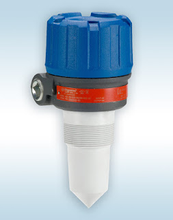
pulse burst radar non-contact level measurement transmitter Magnetrol
Magnetrol Model R82 Radar Level Transmitter
With its ability to reliably detect tank liquid surface level under conditions that prove challenging to other methods, radar technology generally provides an operational advantage over other non-contact level measurement options. Historically, the cost of radar level transmitters for industrial process control applications has hindered their success as a unit of choice for some installations. Magnetrol has changed that imbalance with their recent introduction of a lower cost radar level transmitter for tough applications.

The Model R82 provides radar performance at a price point comparable to competitive ultrasonic units, but maintains the performance advantage inherent in a radar based device. The unit utilizes pulse burst radar technology at 26 GHz, employing advanced signal processing to filter out false echos produced by a range of in-tank conditions that can produce false readings from ultrasonic units.

The short video below provides a closer look at the R82 and its performance advantages. Technical data sheets and any application assistance you may need is available from product specialists. Share your level measurement and control challenges with them and work toward the best solution.

Understanding Instrument Valves

gauge root valve for process control, stainless steel
Gauge Root Valve, a type of
instrument valve
Courtesy Mac-Weld
Process measurement and control employs a wide array of gauges and instruments that may be permanently or temporarily connected to a piping system. Providing controlled isolation and connection of these instruments is the function of what are generically referred to as "instrument valves" or "gauge valves". These valves are generally small, with connection sizes ranging from 1/8" to 1", though there are specialty variants outside this range. The predominant valve type is a needle valve, but ball valves and some other types are also used. Certain attributes of particular applications may weight a selection decision toward a valve type. Widely used throughout the process industries, instrument valves are often designed to accommodate pressures as high as 6000 PSI and are intended for service with gaseous or liquid service.

When selecting an instrument valve, consider construction materials that are compatible with the process media. Additionally, operating temperature and pressure of the process must be well within the limits of the valve.

Instrument needle valves provide reliable function to throttle, regulate and isolate gaseous and aggressive non-viscous liquid services. Product offerings range from simple two-way isolation valves to multiport gauge root valves providing multifunction capability to isolate, calibrate and vent gauge, pressure switches and static instrument applications. Ball valves in this class do not provide the throttling accuracy of a needle valve, but may provide some advantage with the use of certain media. The ball valve design, with its full size port, enables easier cleaning and a lessened potential for clogging.

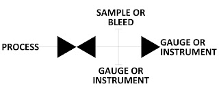
There are three basic configurations of instrument valves. The simplest is the isolation valve with a single inlet and outlet. It provides for selection of exposure or isolation of a connected gauge or other device to the operating process piping or vessel. Maintenance or replacement of the connected device can be effected without opening the contained process to the surrounding environment.

instrument valve schematic isolation valve schematic
Schematic representation of isolation valve

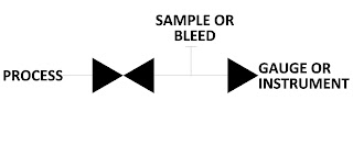
A second variant of instrument valves performs the function of an isolation valve, but has an added port on the outlet side (the side where a gauge or instrument would be connected). The added function of the port is to provide connection access for service, calibration, sampling, purging, or a host of other tasks, all of which can be completed while the process remains in operation.

schematic of block and bleed instrument valve for process control
Schematic representation of block and bleed valve
The third form of instrument valve is a multi-port valve with a single inlet and three outlets. It is often called a "gauge root valve" and serves a number of purposes with its multiple outlet connections. Sometimes two of the ports will be plugged and the instrument or gauge connected to the port providing the most convenient or functional orientation of the connected gauge or the valve handle. This valve can also enable a wide variety of applications through connection of additional instruments, gauges, valves, or other equipment.

schematic of gauge root valve for process measurement and control
Schematic representation of gauge root valve
Share your process measurement and control instrumentation and gauge challenges with application experts and benefit from their expertise.


Accurate Measurement of Very Low Flow Rates Is Key to Compressed Air System Energy Savings

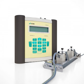
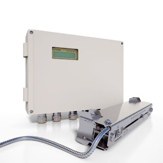
Ultrasonic flowmeter for low flow rates and compressed air
The Flexus G704 CA is specially configured for
measuring flow in compressed air systems
Courtesy Flexim
Operators of plants where compressed air is utilized as an energy source are well aware of the cost associated with continuous delivery of this useful medium. Large or multiple compressors consume considerable amounts of electric power maintaining system pressure and flow requirements. With extensive piping and countless fittings, there are many potential points of leakage. Scheduling of various production operations can vary the demand for compressed air significantly. Getting control of your compressed air system and reducing operating cost is a noble goal. One of the primary tools needed to manage energy costs will be accurate and reliable flow measurement equipment. Here are some characteristics of flow measurement instrumentation that should prove advantageous:

  • Non-invasive measurement from the outer pipe wall that does not add potential leak sources or pressure drop.
  • Availability in fixed or portable configuration.
  • Highly accurate, with paired temperature compensated traceable calibrated transducers
  • Installed without disturbance to piping.
  • Bidirectional measurement
  • Rugged instrument design suitable for any kind of industrial environment
portable ultrasonic compressed air flow measurement instrument
Portable version of specialized ultrasonic flow
measurement instrument for compressed air

Ultrasonic flow measurement technology can provide all of these characteristics, providing
information that enables the operator to make fact based decisions about system design, management, and maintenance. Learn more about how ultrasonic flow meters specifically configured for compressed air system application can help you start reducing your operating cost and developing a higher level of control over your compressed air system. Share your process challenges with a product specialist and work together to build the best solution.