Thermal Mass Flow Meters - Mature Technology With Modern Application

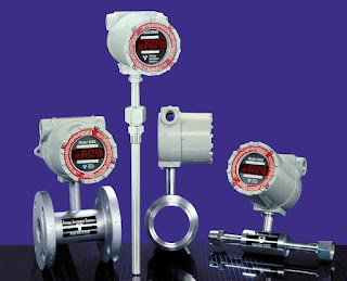
Thermal mass flow meters
Configurations of Thermal Mass Flow Meters
Courtesy Thermal Instrument Co.
Thermal mass flow measurement technology has been used in industrial process measurement and control applications for many years. The technology measures the amount of heat required to maintain a sensor at a constant reference temperature, offsetting the cooling effect of the fluid flow over the sensor. The technology is well suited for installations requiring the measurement of low pressure gases where the fluid components are known and remain constant. Thermal mass flow measurement is also employed effectively in a number of other scenarios.


Potential advantages of thermal mass flow technology for industrial process measurement and control:

  • Provides true mass flow reading using a single instrument
  • Not significantly affected by fluid pressure or temperature
  • Moderate comparative cost
  • No moving parts
  • Minimal restriction of flow introduced by sensor

Typical applications for thermal mass flow meters:

  • Landfill gas outflow measurement
  • Compressed air systems
  • Gas distribution in semi-conductor manufacturing
  • Beverage carbonation
  • Tablet coating and compression in pharmaceutical industry
  • Flare gas measurement in oil and gas industry
  • Natural gas flow to boilers, furnaces, and other consuming equipment
Thermal mass flow sensors have attributes making them very suitable for a family of applications. Like all measurement technologies, there are also areas of caution in their application. Any measurement technology must be properly applied in order to obtain reliable results. Talk to a sales engineer about your flow measurement ideas and applications. Combining your process expertise with the knowledge of a product application specialist will produce good results.


Are You Well Grounded on Grounding? - Part 3

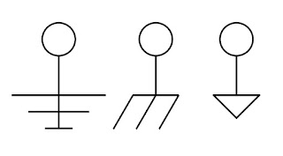
Drawing symbols for Electrical Ground
Electrical Drawing Symbols for Ground
Welcome to the third and final part of this series on electrical grounding for equipment and instruments. Part One and Part Two can be found as previous posts to this blog, and I hope you read them too. Those initial parts provided practical knowledge about equipment grounding and personnel protection in a format understandable to anyone. Those of us more deeply involved with electrical matters likely know someone that could benefit from these articles and I urge you to share.

The white paper that I have included below was produced by the folks at Acromag, a world class manufacturer of signal conditioners and other industrial I/O devices. They have done a fantastic job of presenting technical subject matter in a compact and very understandable form. The subjects covered in the series include:
  • Ground as protection
  • How a ground fault circuit interrupter (GFCI) works
  • Ground as a voltage stabilizer and transient limiter
  • Tips on improving safety and signal integrity
  • The importance of circuit grounding
  • Description of the US AC power system and its use of earth ground
This third installment includes a section entitled "Some Basic Ground Rules For Wired Equipment" which lists out an array of useful tips for connecting wired signals to devices, and more.

Product specialists are always on hand to discuss and solve your process measurement and control issues. Combine the process knowledge of the on site stakeholder with the product and application expertise of the professional sales engineer to produce the best outcomes.


Are You Well Grounded on Grounding? - Part 2

Electrical drawing symbols for ground
Drawing Symbols for Ground
Electricity, like many beneficial trappings of modern society, is both beneficial and dangerous. Protecting users of equipment and appliances from the potentially harmful impact of electric shock is a socially accepted mandate that has been codified everywhere in the developed world.

Acromag, a manufacturer of input and output devices for industrial control systems, has produced a three part series of white papers that provide readable, non-technical descriptions of various aspects of electrical grounding and its relationship to safety and operational integrity. The subjects covered in the three part series include:

  • Ground as protection
  • How a ground fault circuit interrupter (GFCI) works
  • Ground as a voltage stabilizer and transient limiter
  • Tips on improving safety and signal integrity
  • The importance of circuit grounding
  • Description of the US AC power system and its use of earth ground
You can find the initial installment on our previous blog post, and the third installment follows this blog post. All three parts are recommended reading for anyone, but stakeholders in process measurement and control will benefit from refreshing and enhancing their understanding of this important subject. It is a quick read and presents technical subject matter in a way that can be comprehended by anyone.

Product and application specialists are always eager to hear about your application issues and questions. Never hesitate to contact them. Your process knowledge, combined with the product and application familiarity of a professional sales engineer, will generate good outcomes.


Are You Well Grounded on Grounding? - Part 1

Ground Symbols
Some Drawing Symbols Used For Ground
Grounding of electrical equipment and electronic instrumentation is an aspect of project design and implementation that sometimes gets taken for granted. To say that proper electrical grounding is important is an understatement because, without it, certain safety aspects that we rely upon will simply not work. Additionally, and often more confounding, is the intermittent, unexpected, or bizarre behavior of electronic measurement and control devices when proper electrical grounding is not established.

I came across a series of white papers written by some knowledgeable people at Acromag, a manufacturer of industrial input and output devices (industrial I/O). The comprehensive three part series covers best practices involved in the grounding of electrical equipment and electronic instrumentation, in language understandable to a reader of any technical level. The subject matter includes:

  • Ground as protection
  • How a ground fault circuit interrupter (GFCI) works
  • Ground as a voltage stabilizer and transient limiter
  • Tips on improving safety and signal integrity
  • The importance of circuit grounding
  • Description of the US AC power system and its use of earth ground

In my reading of the white papers, I gathered a few things I did not know, refreshed a few I had forgotten, and reinforced my understanding of the topic. There is something in the documents for everyone, and a small investment in time will yield some benefit. All stakeholders in industrial process measurement and control, from the factory floor to the executive office, should have the basic understanding contained in these papers.

Part One of the three part series is below. Part Two and Part Three will be published simultaneously in posts following this one. You can get any level of application assistance you need from the sales engineers that specialize in industrial process equipment, measurement, and controls. Their product knowledge and technical resources, combined with your process mastery, will yield the best solution to any issue.


Big Signal Loop? Consider Using a Splitter.

Acromag Industrial Signal Isolated Transmitter
Industrial Signal Transmitters
Courtesy Acromag
Industrial process measurement and control requires the transmission of signals from point to point with no significant distortion. Even with the growing prevalence of wireless signal transmission, over-wire transmission of signals is still a primary means of connecting one device to another.
In the cabled process measurement and control world, the 4 to 20 milliampere signal is generally considered the standard for transmitting analog control and measurement signals over any distance.
There is an immense array of instrumentation and controllers available for use with 4-20 ma signals, so expertise in routing and delivering those signals should be part of your process M&C skill set.

Like just about everything else, routing 4-20 ma signals presents its own set of challenges that require some thought and planning to overcome. Electrical interference is always a concern and must be prevented from impacting the operation of measurement and control devices. Additionally, there must be sufficient power in the signal loop to accommodate the resistance load of connected devices. There are other considerations, but I'm going to focus on these two.

One scenario that can present significant issues is multiple devices requiring connection to the same signal, but with great distance between them. A simple solution can be implemented using an isolated signal splitter.

Features of these units making them an attractive, single box, solution:


  • One 4-20 ma input channel for the measuring or controlling device.
  • The input signal is retransmitted as identical isolated 4-20 ma signals
  • Galvanic isolation from input to output
  • Isolation between channels for safety and increased noise immunity. Fault in one output channel does not impact the operation of the other channels.
  • Reliable operation in industrial environments, with protection from RFI, EMI, ESD, and surges.
  • Low radiated emissions in accordance with CE requirements. 
  • DIN-rail mounting of the unit
  • Plug-in terminal blocks
If you have a very long signal loop, connecting multiple devices, consider breaking the devices into two groups that may allow for a substantially shorter cable length for each group. Connect each group to one of the isolated outputs of the splitter, giving each group of instruments the identical signal without the risks or impractically of an excessively long cable run.

There are other devices available that may combine special characteristics that solve your signal transmission challenges. Contact a product specialist and discuss your existing or anticipated project requirements. I continually urge engineers to take their process expertise, combine it with the extensive product knowledge of a professional sales engineer, and produce the best possible outcome.


Electric Power Where There Is No Grid

Humankind's quest to continually do more than has been done before takes engineers and technicians, along with their equipment, instruments, and other gear, to all corners of the Earth. Wherever the project goes, electric power will be needed to power it. Unless the needs are short term and very small, a reliable means to produce electric power on site must be put in place to operate equipment, instruments, and other systems necessary for the installation to function as needed.

The potential applications for remote power are vast, ranging from simple land based off-grid locations to ocean platforms, even polar stations. Industrial process measurement and control is found everywhere, which means that sometimes you need to provide the power to operate your own measurement and control equipment. To some, this will be a new challenge to their project management, design, or implementation skills.

Gentherm Global Power Technologies is not only the world leader in thermoelectric generation for remote power systems, they also employ solar and engine driven generator sets in their turnkey systems that can be specifically tailored to your application and installation site. As providers of a wide range of generation technologies, Gentherm is in a unique position to propose the most reliable and cost effective solution for each particular project. Become familiar with this company. You never know where your next project may be located.

A short video, included below, will get you started. You can also contact a product specialist to discuss any aspects of applying the technology.


Delivering Electric Power to Remote Sites

Thermoelectric Generator
Courtesy Gentherm
Industrial companies accomplish some amazing feats in some very inaccessible and remote places. If you are in the natural resource business, you go where the resources are to extract them from the earth. The telecommunications industry locates equipment where needed to forge links and deliver signals. Environmental monitoring, navigation aids, buoys, lighthouses, and airstrips can all be situated in areas without grid power. Often, these installations are unattended, and require continuous reliable electric power to operate. When there is no grid to which the installation can be connected, a challenge arises regarding how to provide electric power to the site equipment.

There are several possible solutions for providing remote power, each with its own set of operating attributes which may make it more or less suitable for any particular application. When considering a remote power generator, you should include thermoelectric generators on your list of prospects.

Thermoelectric generators convert heat directly into electricity using a fuel source for heat, a hermetically sealed thermopile, cooling fins, and no moving parts. These generators are a positive and cost effective solution for remote power requirements, having operational and cost benefits over engine driven generators, batteries and solar sources for many applications.

The short document below provides an overview of thermoelectric generator operation and application. Talk to a product specialist about your need to power a remote site. A thermoelectric generator may be an option you had not considered, but may prove to be the best solution.