Process and Equipment Monitoring Using Telemetry

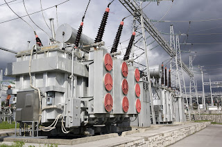
high voltage transformers in electrical substation
Continuous monitoring of remotely located
equipment yields a wide range of benefits
Industrial operations and processes are populated with unimaginable variations of equipment and applications, each with specific operating sequences intended to produce a specific outcome. By their scale and nature, most have the capacity to substantially impact the success of the organization. As stakeholders in the operation of industrial processes and equipment, we have an interest in monitoring their performance for any number of reasons.

  • Financial - The investment in plant and equipment is financially significant to a company of any size. An operator benefits from monitoring process inputs and outputs. Scrutinizing the operating status of process equipment and intermediate process conditions provides valuable information that can be used to minimize negative events of many types.
  • Maintenance - Keeping a real time watch over operating characteristics of machinery can present opportunities to head off trouble before it happens. There are many warning signs that can precede equipment failure, and taking prompt remedial action requires issuance of real time warnings.
  • Safety - Industrial operations of all types tend to exhibit levels of hazard to personnel or environment ranging from minor to potentially catastrophic. The rigorous procedures employed to maintain operation within prescribed limits are enabled through the use of information about process conditions.
  • Regulatory - There can be jurisdictional requirements to monitor and report certain process characteristics. An ability to conduct the needed action from afar, without having to station personnel at a remote location, has some real benefit.
This list is not intended to be complete or definitive. There are countless ways that process operators can use real time data to enhance all facets of their operation. A challenge arises when the process or operation extends over a large area, perhaps beyond the boundaries of the primary facility. That's where telemetry serves as the means to deliver needed information to a decision making location.
Modern requirements for "knowing what is happening" increase the need for telemetry in industrial operations. 
Telemetry is getting the information you need from a remote or inaccessible location and delivering it to where it can be used for decision making. 
With the wide array of hardware offered by process measurement and control equipment suppliers, implementing the data collection and transmission has become a fairly straight forward task. Simply put, here is what you need to accomplish.

  • Measure or detect the information needed. You know how to do this. Sensors, counters, or other regularly available process measuring equipment is what is needed here.
  • Convert the measurement into a transmissible form. This will likely be accomplished by the transmission gear. The measurement devices you use should provide an output signal that is compatible with the input requirements of the selected transmission equipment.
  • Transmit the information to the receiving station (the decision making point). The device and equipment manufacturers do most of the hard work of accomplishing this task. Generally, regardless of the transmission method, the extent of the work needed to put transmission into operation involves powering up the equipment and assigning addresses or channels to identify the source of the signal.
  • Receive the signal and convert it to a form readable by the decision making portion of the system. Again, the telemetry equipment manufacturers handle the details in the design of their equipment. Implementation consists of similar steps to those of the transmission equipment.
It is recommended that the transmission method be selected first. It must accommodate any challenges presented by the distance to be covered and any obstacles that may impact the delivery of the signal to its destination. Coordinate the measuring device output signal selection with the transmission device input requirements. The receiving equipment must be capable of producing an output signal that is readable by whatever decision making or recording equipment is used.

Below is a case study illustrating how a user derived a signal from a utility plant to provide data on local power consumption.You will see how they selected and employed equipment to accomplish the four tasks outlined above.

The applications are only limited by your imagination and ingenuity. Instead of wondering about what is happening at remote locations, operators can now easily measure and deliver useful operating information across almost any distance. Share your challenges with process control specialists and develop the solutions you need.


Improved Gauge Visibility With New Product Feature From Wika

luminous glow in the dark instrument gauge
Wika Instrument gauges have optional high visibility feature.
Wika Instrument, a world class manufacturer of temperature, pressure, level, and flow instrumentation for the industrial process control field, has introduced a product innovation that allows operators to observe gauge readings in low light conditions. The product enhancement comes in two forms, called InsightTM and Insight GlowTM. I have inserted the manufacturer's published description of both options below, along with a video that demonstrates the Insight GlowTM in low light conditions.

More detailed information, along with application assistance and product configuration, is available from an experienced Wika distributor. Use your process expertise and their product application knowledge to achieve the best solutions to instrumentation challenges.

From the company:
InSightTM
The InSightTMoption includes a retro-reflective material affixed to the dial face. At daylight, the fluorescent color absorbs non visual UV light reflecting additional light and making the gauge even more visible. At low light, the pattern of the retro-reflective material also makes the dial more visible to stand out among other regular gauges.
This easy-to-view option comes in three colors: white, fluorescent yellow, and fluorescent orange. It is currently available on industrial and process type gauges (SS wetted parts) and bimetal thermometers for both dry and liquid-filled case options, in sizes from 2 ½” to 6” in diameter.
InSight GlowTM
The InSight GlowTM option uses a retro-reflective, photo-luminescent dial design that illuminates the entire front of the instrument dial for an extended amount of time when exposed to a light source for as little as 10 seconds. The dial appears bright white in darkness, fog, smoke, and fire.
Like the InSightTM option, the Glow is also available on industrial and process type gauges (SS wetted parts) and bimetal thermometers for both dry and liquid-filled case options, in sizes from 2 ½” to 6” in diameter.
Additional Factors to Consider
WIKA has developed additional options to enhance the readability of gauges. For example, a magnification window enables instruments to be read from a distance. An anti-glare window eliminates unwanted reflection of sunlight or bright indoor lighting.
For any gauge, dial size is also a key specification that can aid in readability. Accurate information allows you to operate safely and efficiently. Where possible, WIKA recommends a minimum size of four inches in diameter for process gauge dials. This enables them to be easily read from three to six feet away.

Unique Cybersecurity Challenges For Industrial Control Systems

industrial control system cybersecurity
Industrial control systems have special
cybersecurity aspects.
The International Society of Automation is offering a free white paper entitled “What Executives Need to Know About Industrial Control Systems Cybersecurity”. The article provides useful commentary and information that establishes the scope of cybersecurity in the industrial process control space and provides a basic framework for understanding how every process may be impacted by lax cybersecurity efforts. The author, Joseph Weiss, differentiates Industrial Control System (ICS) cybersecurity from that of organizational IT through a review of various attributes common to both types, including message confidentiality, integrity, time criticality, and more. Any reader’s awareness and understanding of the cybersecurity risks to their operation will be enhanced through this article. I finished reading the article wanting more on the subject, and ISA is certainly a resource for additional content.

A quote from article...
“Cyber incidents have been defined by the US National Institute of Standards and Technology (NIST) as occurrences that jeopardize the confidentiality, integrity, or availability (CIA) of an information system.”

ICS cybersecurity extends beyond preventing malicious outside intruders from gaining access. It is an important part of maintaining the overall operating integrity of industrial processes. A holistic approach is advocated to identify physical risk factors to the process and its componentry (subject of a previous blog posting), as well as vulnerabilities that may prevent exploitation by unauthorized parties. Weiss goes on to describe the role and qualifications of the ICS Cybersecurity Expert, essentially an individual that can function effectively as an IT cybersecurity tech with the added skills of an industrial control systems expert.

A synopsis of attack events is provided in the article, with the author’s conclusion that not enough is being done to secure industrial control systems and the risk exposure is substantial in terms of potential threats to personnel, environment, and economy. By providing your name and email address, you can obtain the white paper from the ISA website. Your time spent obtaining and reading the article will be well spent.

For any specific information or recommendations regarding our products and cybersecurity, do not hesitate to contact us directly. We welcome any opportunity to help our customers meet their process control challenges.


Orion Instruments Announces New Level Transmitter

Direct insertion and external mount versions of
Orion JM4 Magnetostrictive Level Transmitter
Courtesy Orion Instruments
Orion Instruments, a world class manufacturer of magnetic level indicators, level switches, and level transmitters, has released a new product for use in the industrial process measurement and control field. Their Jupiter Model JM4 magnetostrictive transmitter incorporates the company's many years of research, development, and field experience to provide a safer, simpler, and smarter transmitter for liquid level measurement and control.

The new model from Orion boasts level measurements with accuracy as high is +/-0.05" (1.27mm). The transmitter head can be rotated up to 310 degrees with an option for remote mounting. Variants are available for direct insertion or external mounting, with approvals for a number of area classifications. There are other valuable features to this series of level measurement instruments that reflect Orion's expertise in the field.

Browse the new product brochure included below. It provides illustrations of the product and its operating principle, along with dimensioned drawings and a listing of all the product options and variants. You can always obtain whatever information you need about Orion level measurement instruments from a product specialist. Share your liquid level measurement challenges and requirements with them for recommendations on the best solutions.


Cavitation Induced by a Control Valve - Demonstrated


Consider a generic industrial fluid process control operation. There are pumps, valves, and other components installed in the process lines that, due to their interior shape or their function, cause changes in the fluid motion. Let's look specifically at control valves and how their throttling operation can create conditions able to greatly impact the valve itself, as well as the overall process.

Fluid traversing a control valve can undergo an increase in velocity when passing the constriction presented by the valve trim. Exiting the trim, fluid then enters the widening area of the valve body immediately downstream with a decrease in velocity. This change in velocity corresponds to a change in the kinetic energy of the fluid molecules. In order that energy be conserved in a moving fluid stream, any increase in kinetic energy due to increased velocity will be accompanied by a complementary decrease in potential energy, usually in the form of fluid pressure. This means the fluid pressure will fall at the point of maximum constriction in the valve (the vena contracta, at the point where the trim throttles the flow) and rise again (or recover) downstream of the trim.

Here is where cavitation in control valves begins.

If the fluid being throttled is a liquid, and the pressure at the vena contracta is less than the vapor pressure of the liquid at the flowing temperature, portions of the liquid will spontaneously vaporize. This is the phenomenon of flashing. If, subsequently, the pressure of the fluid recovers to a level greater than the vapor pressure of the liquid, any flashed vapor will rapidly condense, returning to liquid. This collapse of entrained vapor is called cavitation.

Flashing, the generation of vapor bubbles within the liquid, will precede and set the stage for cavitation. When the flashed vapor bubbles condense to liquid they often do so asymmetrically, with one side of the bubble collapsing before the rest of the bubble. This has the effect of translating the kinetic energy of the bubble’s collapse into a high-speed “jet” of liquid in the direction of the asymmetrical collapse. These liquid “microjets” have been experimentally measured at speeds up to 100 meters per second (over 320 feet per second). What is more, the pressure applied to the surface of control valve components in the path of these microjets can be intense. An individual microjet can impact the valve interior surfaces in a very focused manner, delivering a theoretical pressure pulse of up to 1500 newtons per square millimeter (1.5 giga-pascals, or about 220000 PSI) in water. In an operating fluid system, this process can be continuous, and is known to be a significant cause of erosive wear on metallic surfaces in process piping, valves, pumps and instruments. As the rapid change in pressure takes place, the bubbles (voids in the liquid) collapse (implode), and the surrounding metal surfaces are repeatedly stressed by these implosions and their subsequent shock waves.

Consequences for control valves, as well as for the entire control process, vary and are often destructive. They may include:
  • Loud noise
  • Strong vibrations in the affected sections of the fluid system
  • Choked flow caused by vapor formation
  • Change of fluid properties
  • Erosion of valve components
  • Premature destruction or failure of the control valve 
  • Plant shutdown
The video provides a visual demonstration, through clear piping, of what happens inside the piping system when a valve is operated in a manner that causes substantial cavitation.

The solution lies in minimizing the potential for cavitation to occur through proper valve selection and sizing, along with coordinating operating characteristics of pressure drop inducing components with the total system performance. One valve manufacturer's recommendations are summed up in four basic approaches.

  • Avoidance of cavitation through proper valve selection. Use a valve with a rated liquid pressure recovery factor greater than that required for the application. Some applications may be suitable for the use of an orifice plate downstream of the valve.
  • Cavitation Tolerant Components capable of withstanding limited amounts of cavitation without excessive wear. Increased flow noise is likely to accompany this route.
  • Prevention of cavitation through the use of valve trim design that reduces pressure in several steps, avoiding excessive flashing. These valves can be expensive, but their effectiveness makes them an alternative worth considering.
  • Containment of the harmful effects of limited to moderate cavitation through trim designs that eliminate contact of the fluid with metal surfaces which are more susceptible to damage.

Share your requirements and application challenges with a valve specialist and gain insight through their recommendations. Combining your process knowledge with their product application expertise will yield a great solution.

Knowledge Base and Selection Guide For Magnetic Level Indicators

Orion Instruments Magnetic Level Indicators
Magnetic Level Indicators
Courtesy Orion Instruments
Industrial process control frequently involves the storage of liquid in vessels or tanks. Continuous and accurate indication of liquid level within the tank is an essential data point for safety and process management. While there are a number of methods and instrument types utilized to provide tank level measurement, the instrument of choice is often a magnetic level indicator, also referred to as a magnetic level gauge. Its use for providing level indication has a number of positive attributes:
  • Construction that is resistant to breakage.
  • Measuring indicators, switches, and transmitters mounted externally, without contacting the medium being measured.
  • Maintenance free operation. No regular cleaning needed.
  • Readable level indication from greater distance than glass sight gauges.
  • Magnetic level indicators can accommodate greater fluid level ranges without the need for multiple instruments.
Orion Instruments, a Magnetrol company and industry leader, has produced a comprehensive guide to magnetic level gauges, switches, transmitters, and related products. It delivers experts and newcomers an understandable and clear description of the technology and principals of operation behind magnetic level gauges and instruments. The guide also assists the reader in properly specifying and selecting the best instrument configuration for an application. A table of contents at the front of the document helps readers to quickly find the information they need.

Take a couple minutes to roll through the document and you are likely to find new and useful application tips and product information. Any questions about magnetic level indicators or your process measurement and control applications can be clearly addressed by a product specialist.


Filtration Yields Returns By Protecting Fluid Process Lines and Equipment

Dual basket strainer with changeover valve
Duplex Basket Strainer With Diverter Valve
Courtesy Eaton Filtration
Most people think of "industrial" equipment as super heavy duty, virtually indestructible. Those of us responsible for operating and maintaining industrial process equipment recognize that is not the case. Even the most formidable appearing equipment can be crippled if not protected from the insidious effects of particulates.

There are numerous strategies for mediating the impact of particulates on industrial fluid process equipment and systems. The best solutions will be customized for each process, with consideration given to:
  • Maximum particle diameter threshold: At some level, particulates may be small enough to preclude damage to the system. Above the threshold level, removal of the particles brings some benefit to process operation.
  • Pressure drop associated with any mitigation techniques: Assuming that mitigation will involve the addition of components to the fluid system, minimizing the added pressure drop is advantageous.
  • Overall volume of particulate matter to be removed: Most often, mitigation equipment traps and retains particulate matter. The retaining capacity of the unit must match the particulate production rate of the process. Be mindful that certain events, such as routine maintenance or cleaning of process equipment, may produce surges of particulates in some types of systems.
  • Location of the filtration equipment: Filtration units must be placed in the process flow upstream of the equipment or system portion to be protected. An additional consideration is a provision for maintenance through placement in a convenient, easily accessible location.
  • Filtration equipment materials of construction: The filtration gear must be fabricated of materials compatible with the process media.
I have provided a data sheet below with cutaway illustrations and detailed performance data for one type of filtration unit. This particular equipment is manufactured by the filtration division of Eaton and features a duplex strainer basket arrangement with a diverter valve. The process fluid flows through one strainer, with the other clean and ready to be brought on line when the active basket becomes clogged. When the active basket becomes clogged and pressure drop excessive, the operator moves a lever to divert the flow to the second basket, sealing off the now clogged basket area so that it can be opened and cleaned. This design provides for uninterrupted process operation.

Browse the provided data sheet. You will likely pick up something you did not already know, or get a quick refresh of your technical knowledge. The duplex basket strainer is one type in a wide variety of filtration products available for every conceivable process application. Share your challenges with a product specialist. Combining your process knowledge and experience with their thorough product application expertise will generate great solutions.