Use of Thermal Dispersion Flow Switches for Pump Protection

thermal dispersion flow switch
Model TD2 Thermal Dispersion Flow Switch
Image courtesy Magnetrol
Thermal dispersion flow switches use an operating principle similar to that of a thermal mass flow meter. Moving fluid carries heat away from the probe tip reducing the temperature difference between a heated resistance temperature detector (RTD) and a reference RTD. Unlike a flow meter, a thermal dispersion switch operates with setpoints, comparing the detected flow rate to the setpoints and controlling a relay or other digital output in response. Manufacturers will refer to the switch being in “alarm” at set point. How the relay is wired (NC-CO or NO-CO) depends on the needs of the application.

High or low flows can be detected by thermal dispersion switches. While thermal dispersion flow measurement technology is applicable for gases and liquids, pump protection is the subject of this post, and reference will be limited to liquid flows and low flow detection.

Running pumps with inadequate liquid throughput is well recognized as a source of excessive wear, parts damage, cavitation and downtime due to repair. The cost of replacement parts, repair labor and lost production time can ramp up very quickly.
Monitoring liquid flow rate and triggering an alarm or pump shutdown to prevent damage has substantial benefit, even in a system of comparatively modest size.
There are many technologies that can measure liquid flow and function as part of a pump protection scheme. Flow meters can be used, but a continuous flow measurement may not be needed for the application. Flow meters typically are more costly than flow switches.

Mechanical flow switches are an alternative. Prior to the availability of electronic controls, they were generally the only method employed. They use a mechanical operator, driven by liquid flow, to actuate a relay. Typically, a vane or paddle is in the flow stream and swings in the direction of the flow. When the vane moves a predetermined distance, a magnetic sleeve or other device rises to draw the magnet in to actuate the switch. Moving parts are subject to wear, possible jamming and increased maintenance over time. Viscous liquids or those that may accumulate deposits on the operating mechanism can decrease reliability of the switch. A mechanical flow switch may be desirable if there is limited on-site power. In terms of the installation, the pipeline must be horizontal.

Vibrating forks and ultrasonic gap switches are other technologies employed for pump protection. It is inherent in these technologies that the presence or absence of liquid at the sensor location is all that is detected, not actual fluid flow. They are unable to detect decreasing flow rates, and their "gap" at the sensor creates opportunity for plugging or fouling with some liquids. Common applications for these switches are sumps or wet wells. Dual ultrasonic gap switches have pump control modes where the unit performs auto-fill or auto-empty as needed. 

Thermal dispersion flow switches deliver a robust feature set and application flexibility.
  • No moving parts
  • Low maintenance burden 
  • Range of probe types to accommodate water or more viscous liquids 
  • Installation in horizontal or vertical lines
  • Variety of mounting types and insertion locations 
  • Optional remote mount electronics
  • Hot tap options available
  • Low flow detection as opposed to dry pipe 
  • Current output for trending and fault indication
  • Temperature compensation to reduce set point drift under varying operating temperatures 
Probe Types

The standard probe design offered by thermal dispersion switch manufacturers is a twin tip construction to house the sensors. The twin tip is essentially two tubes welded to the end of the probe that are in the process liquid.

Twin tip probes can be beneficial as multiple manufacturers have similar designs. It has a very high pressure rating and is available in a variety of construction materials.

A unique design that may be preferred for liquid applications is the spherical tip probe. The lack of pins at the end of the probe eliminates plugging in viscous applications while the thin wall allows increased sensitivity with the process liquid. With pressure ratings up to 600 psig (41 bar) and standard 316 stainless steel material of construction it is suitable for most pump applications.

Electronics

The electronics for the thermal dispersion switch can be integral to the probe assembly or remotely located, enclosed in an explosion proof or other suitable housing. Wiring is simplified with the terminals easily accessible without removal of the bezel or any circuit boards. Along with the ease of installation come many diagnostic features incorporated in the microprocessor based electronics.

A useful diagnostic feature in the electronics is the current output. It is not a linear 4-20 mA output, similar to a flow meter, but the current will act as a live signal that varies with heat transfer. For example, in a low flow condition the current may be 8 mA and at normal flows 12 mA (output varies for each application). The current will be repeatable for a given low flow set point. If there is turbulence in the line, possibly being caused by a closed valve with the pump still running, the sensor will see this turbulence as a higher flow rate than what is actually occurring. The live signal allows the operator to monitor conditions to which the sensor is exposed and possibly develop custom diagnostics for the fluid system.

Along with the trending capabilities of using the current output, this output will also go low or high when a fault condition occurs according to NAMUR NE 43. For pump applications where a low flow alarm is desirable, the current will fall to less than or equal to 3.6 mA during the fault. The microprocessor based electronics monitor for any open circuits or flow signal that goes out of range. Without a microprocessor, the flow switch could be subject to more noise, have drift issues and need more frequent calibration to maintain the set point.

The user also has the option to select a window in the housing of the electronics. This window allows viewing of the LEDs to show normal operation (relay energized), alarm/set point (relay de-energized) and fault conditions (relay de-energized). Switch and process operation can be confirmed locally at a glance.

Because the principal of operation of thermal dispersion switches is temperature dependent, temperature compensation is provided in the electronics circuitry. Temperature compensation will reduce set point drift under varying operating temperatures.

Pump Installations

Both positive displacement and centrifugal pumps have performance curves to maximize efficiency. There is an ideal combination of differential head and flow rate that will provide the best results. If monitoring the differential head, a thermal switch can be set up to shut the pump down when it is operating below the ideal flow rates. Worst case scenario, the thermal switch is installed to verify there is liquid flow to prevent excessive wear or failure.

Installing the thermal switch in either the suction or discharge piping is acceptable. It is important to install in a location where the sensor tip will be exposed to liquid movement, especially in the case of a partially filled pipe. When field calibrated, which is most often the case for thermal switches, it is not necessary to install at the centerline of the pipe. As long as the probe is far enough into the pipe to see liquid movement, it will provide repeatability at the given flow rate. A quarter to half way into the pipe is common.

Installing a few diameters away from the pump will reduce the impact of excess turbulence. Turbulence may cause the switch to sense higher flow rates than what is actually occurring inside of the pipe. Movement of liquid due to turbulence can theoretically create as much heat transfer as the liquid flow itself. The aforementioned current output is a helpful diagnostic feature in more difficult installations.

Summary

Thermal dispersion switches are used in pump protection applications ranging from standard water to high viscosity liquids. There are unique sensor designs for each individual application, including the popular spherical tip, low flow bodies and high temperature/pressure probes. The multitude of probes in conjunction with the advanced electronics make thermal dispersion switches a competitive technology for pump protection.

Share your fluid flow challenges with process measurement specialists. Leverage your own knowledge and experience with their product application expertise to develop effective solutions.
Process Measurement and Control Devices for Corrosive Environments

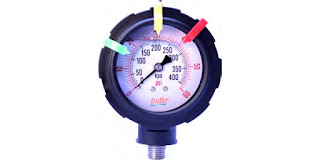
all plastic industrial process measurement corrosion resistant pressure gauge
All plastic corrosion resistant pressure gauge.
Image courtesy ICON Process Controls
ICON Process Controls specializes in corrosion resistant industrial fluid handling process control equipment, offering industry the most complete line of instrumentation products in an all plastic form supported by the largest inventory in North America. Applications for corrosion resistant instrumentation and controls are found throughout...
  • Municipal and industrial water and wastewater treatment
  • Bulk chemical storage, handling and production
  • Steel processing
  • Metal Finishing
  • Chemical Dosing Skids
  • Food and Beverage processing and production
The ICON product line handles tasks for measuring and controlling flow, level, pressure, and temperature in environments that are otherwise challenging or corrosive to other process instruments. Their unique all plastic construction makes the ICON equipment and instruments particularly well suited to the harshest industrial environments.

For information about the complete line of corrosion resistant industrial fluid handling process control equipment from ICON, reach out to the process control experts at MS Jacobs. Share your process control challenges and leverage your own process knowledge and experience with their product application expertise to develop effective solutions.


Measurement and Control Products for the Shale Gas Industry

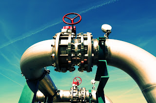
steel shale gas pipeline with valve
M.S. Jacobs provides measurement and control solutions
to the shale gas production and processing sectors.
Several areas of North America are involved with the extraction of shale gas resources. The Marcellus Formation, one of the largest shale gas production areas, is located beneath much of the coverage area of M.S. Jacobs & Associates. A substantial portion of the company's product lines have application potential throughout the layers of the industry.

The Gentherm Global Power Technologies TEG (thermo-electric generator) is a product M.S. Jacobs provides for “upstream” use on the production well pad. It provides a reliable source of electric power at off-grid locations and is preferred because of its reliability and operating principle. A TEG has no moving parts and requires little maintenance. A thermoelectric generator converts heat directly into electricity. As heat moves from a gas burner through a thermoelectric module, it causes an electrical current to flow. Thermoelectric generators are a preferred source of power in areas without reliable and abundant sunshine for photovoltaic production of electricity.

Another source of remote power are the Stirling Engine driven generators from Qnergy. Operating on any combustible fuel, these systems deliver electric power efficiently and require no maintenance. The Qnergy power units are fuel agnostic and insensitive to gas content, able to run on gas with variable caloric content.

M.S. Jacobs is also involved with solutions for midstream operations. Flexim ultrasonic clamp-on flowmeters serve as check meters at midstream processing facilities and compressor stations to measure large volumes of gas. They are also being used to help balance the load to the compressors. Other applications are on gas storage wells that are filled in the summer and pumped out in the fall-winter, taking advantage of the bi-directional measurement capability of the meter.

M.S. Jacobs also provides Magnetrol level controls and Orion visual level indicators for various level applications as well as valves and controls on other midstream and downstream applications. A primary partner to many processing companies, M.S. Jacobs provides experience, application expertise, local inventory, and ongoing support.

Share your process measurement and control challenges with application specialists, leveraging your own knowledge and experience with their product application expertise to develop effective solutions.

Expansion Joints in Process Piping Systems

Expansion joints relieve stress on process piping
Expansion joints accommodate the movement in piping systems
due to a number of real world factors.
Image courtesy General Rubber Corp.
Piping systems of any size require consideration of stresses placed upon the system by movement resulting from a number of possible factors. In some cases, the movement is vibratory and related to the operation of connected machinery. Another common case is the expansion and contraction of piping sections due to thermal effects.

Process piping can have substantial stress applied due to thermal expansion of the piping material itself. This is especially evident when portions of the process piping are fixed in position by their mounting method. Allowances must be made for expansion of the piping material in the installed location. The design criteria will include factors that impact the expansion of the piping components, as well as the relationships between the piping and elements of their supporting structures. Expansion can produce substantial movement of pipe sections which must be accommodated by the supports and the piping itself.


One manufacturer, General Rubber Corp., manufactures a wide range of expansion joints for process piping systems of almost any size. Their expertise, acquired over many years in the field, is reflected in the numerous product variants available to meet every application condition.

Share your process piping challenges with product specialsts, leveraging your own knowledge and experience with their product application expertise to develop effective solutions.


One, Two, or Three Piece Ball Valve?

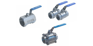
one piece, two piece, and three piece ball valves
Examples of one, two, and three piece ball valves.
Image courtesy Duravalve
Ball valves are employed throughout many commercial, institutional, and industrial venues where the need to isolate part of a system is necessary, or even just to regulate the on/off condition of system fluid flow. The product variants are almost uncountable, with a version to accommodate almost any application.

When selecting a ball valve, one facet of construction will be evident in your research. There are three common types of ball valve construction; one piece, two piece, and three piece. Here are some general considerations and differences among the three types.

  • A one piece ball valve has a body and end connections formed from a single piece of material. This construction presents a comparatively reduced number of opportunities for leakage. The valve trim and seals are inserted through one of the end connections. This type of valve will not have a port size equal to the line size. The simplicity of the one piece body design tends to make their cost lower than the other versions. Once the valve is in place, it cannot be serviced without removing the entire valve assembly from the piping system.
  • Two piece ball valves generally have one piece that includes an end connection and the body, plus a second piece that fits into the first that will hold the trim in place and provide the second end connection. The construction presents an additional leak potential where the two pieces are joined, but also allows disassembly of the valve for replacement of the internals. These valves can provide full port service and bidirectional flow shutoff.
  • A three piece ball valve essentially separates the connection portions of the valve assembly from the body of the valve. These will be more expensive than either of the other two types, but their allowance for removing the valve body and trim from the piping system while leaving the connections in place may prove valuable for many applications. Full port and bidirectional shutoff can be provided by this construction.
Properly applied, all these valves will provide good service. Your selection depends on the demands of the application. Share your fluid measurement and control requirements and challenges with process control specialists, leveraging your own knowledge and experience with their product application expertise to develop effective solutions.

Blowdown Tanks in Steam Systems

schematic of boiler blowdown tank with thermostatic cooling valve
Schematic for applying blowdown tank in steam system.
Image courtesy Colton Industries
Blowdown, in a steam system, serves as a means to remove condensate or reduce the accumulation of minerals and contaminants in a boiler. The temperature and pressure of the effluent precludes its discharge into most municipal sewers, requiring a means to collect the discharge and reduce its temperature prior to final disposal.

A blowdown tank is designed as a receiver which vents flash steam to atmosphere and provides for cooling of the condensate prior to final discharge. A vent connection at the top of the tank is normally routed to a safe discharge location outdoors. In some cases, a condenser may be applied to the vented steam. The condensate collects in the tank and cools as heat is radiated from the tank walls, generally steel or stainless steel. Faster cooling can be accomplished with the incorporation of a thermostatic cooling valve that mixes cold water with the condensate.

The blowdown tanks have no moving parts and few requirements for maintenance. Good practice calls for periodic inspection for wall erosion and corrosion. An inspection hatch provides access to the tank interior.

Share your steam system requirements and challenges with specialists, leveraging your own knowledge and experience with their product application expertise to develop effective solutions.


Storage and Process Tanks

industrial sanitary stainless steel process tanks
Industrial process tanks use measurement instruments
to reveal the nature of their contents.
Storage and process tanks are employed throughout a broad range of industrial, research, and commercial applications. The design and construction of the vessels varies widely, but there are a few measurement and control functions common to almost all applications. Whether general purpose or very specialized, a process or facility operator with a tank will need to know…
  • Nature of the contents. What is in the tank.
  • Quantity of material in the tank. This can be expressed as weight, mass, level or volume.
  • Condition of the material in the tank. This can include temperature, pressure, or a range of other specific attributes which may have a bearing on the process or operation for which the material is to be used or applied.
Instrumentation and fixtures of varying styles and types are used to provide information relating to the three areas noted above. A broad range of tank level measurement techniques and instruments are employed to quantify tank contents. Specialized sensors can be used to measure conductivity, pH, and a host of other material aspects.

Industrial storage tanks are used as containers for everything from water to fuels to chemicals. Contents may be pressurized or blanketed with ignition suppressing gases, such as nitrogen. The construction of a process tank must meet requirements for safety and functionality related to its specific use. Well known commercial applications include those in food, beverage, and dairy sectors. Every industrial or commercial use will have standards for physical safety, product safety and quality, as well as requirements for effective integration into whatever system the application presents.

Mixing tanks perform a different function in the control process as opposed to storage tanks. Mix tanks are involved in batching and blending processes. Made of glass, plastic, sturdy rubber, or stainless steel, mixing tanks blend different substances together to create materials for production. The refined mixing process occurs as certain amounts of liquids are funneled into the tank from lines leading to the tank. The tanks may be provided with specialized fixtures or apparatus to facilitate the combining of constituent substances. Depending upon the application, the components may not all be liquid.

The term “tanks”, per se, encompasses practically an entire industry in itself. The variety of sizes, forms, materials, and accessory features is enormous. Share your tank instrumentation and measurement challenges with process measurement specialists, leveraging your own knowledge and experience with their product application expertise to develop an effective solution.

Comprehensive Planning for Heat Trace and Surface Heating Challenges

refinery with workers
Applications for process heating are numerous and varied,
found throughout industrial and commercial settings. 
Keeping process or inventory liquids from freezing, or becoming extremely viscous, can be an important part of a commercial or industrial operation. Freeze damage to equipment, piping, containers or their contents can result in a wide array of consequences, all of them likely to be negative.

Developing an overall plan for freeze protection can be advantageous to attacking each application on an independent basis.
  • Having a common vendor for all freeze protection equipment and supplies can help designers develop a knowledge base about how to meet application challenges with specific products, speeding implementation time. Service techs become familiar with applied products and methods, building their skills and efficiency at installing and maintaining applications throughout the facility.
  • Identify all locations where freeze protection is needed. Develop a baseline of the methods employed and equipment installed to meet the needs of each location. Good records form the basis for good maintenance and the ability to make decisions regarding the operation and performance of each system.
  • When selecting the products or methods to employ for freeze protection, consider the environment in which the hardware will be installed. Will it require protection from physical damage, chemical attack, or extreme weather. Is the installation space considered a hazardous zone, requiring special certifications for the heating equipment?
  • The availability and control of applied heat can also be important. Is there a need for the heating system to deliver highly variable amounts of heat across the range of possible operating scenarios, in order to avoid overheating the process or stored materials? How quickly will the system need to ramp up to the desired operating temperature or respond to changes in an operating process?
These questions, and probably others specifically related to your application, should be part of the consideration for freeze protection applications. Enlisting the cooperation of a process heat specialist can apply leverage to your own process knowledge and experience to develop an effective solution to each challenge.

Check this link and request a copy of the Freeze Protection Planning Guide.

The Possible vs. The Probable

Overhead view of the Arkema plant in Corsby, Texas.
Image from United States Chemcial Safety Board 
Process stakeholders have concerns and responsibilities regarding operational safety, environmental impact, profitability, and more. At almost every level, the risk of loss, damage, or disaster is scrutinized and evaluated. Steps may be taken to prevent or reduce the impact of some negative event. Other risk reduction methods might be put into play to provide relief from losses suffered. Whatever the case, it is safe to say that much industrial effort is invested in predicting a broad range of "what if" scenarios.

The recent events at the Arkema chemical plant in Crosby, Texas bring to light the limitations we, as process operators of any type, may put on our own thinking and actions. Though investment was made, and was ongoing, to improve aspects of the plant, the operation was still brought to a standstill and a fire ensued that brought the involvement of the US Chemical Safety Board. This resulted because natural events that were likely deemed impossible became reality, with insufficient contingency operations in place to handle the situation.

What is important about the event is what we can all learn from it, what we can use to modify and improve our own methods of evaluating risk and implementing protections to prevent loss and damage. Essentially, the plant was overwhelmed by storm induced flooding that was unprecedented. Grid and backup power sources were rendered inoperable and material that required refrigeration to maintain a safe condition no longer was provided with the needed cold storage environment.

arkema chemical plant timeline hurricane harvey US chemical safety board
Timeline of events related to a fire at the Arkema chemical plant in Crosby, TX
Image is from US Chemical Safety Board 
The relationships between an operation and its surrounding environment are not static. The probability of any event occurring is never zero. When probabilities are perceived as being very small, they might be ignored, but low probability events can and do eventually become part of the plant environment. Developing strong contingency plans and incorporating design elements into an operation that account for events that seem impossible, but are actually of very low probability, is a good industrial practice that hardens the process or facility against disaster.

Share and discuss your concerns and plans with process instrumentation and control specialists, leveraging your own knowledge and experience with their resources to develop a better solution.