Showing posts with label Western Pennsylvania. Show all posts

M.S. Jacobs & Associates - Equipment Engineers

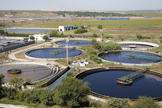
aerial view wastewater treatment plant settling ponds
Wastewater treatment is one of the many industrial sectors
served by M.S. Jacobs
M.S. Jacobs and Associates has been a leading manufacturer's representative and distributor of industrial instrumentation and controls since 1945. Expanding from its original focus on the steel industry, MS Jacobs services and supplies products in all major industrial markets, including power generation, chemical processing, pulp and paper, oil and gas production, water and wastewater treatment, and nuclear power generation.

The company's longevity and dedication to the industrial market has resulted in a broad offering of superior quality products for flow, level, pressure, and temperature measurement, as well as filtration products and valves. Everyone at MS Jacobs takes pride in the company's ability to solve tough applications and provide exceptional customer service with a team of trained outside sales engineers and inside customer service representatives.

MS Jacobs' Pittsburgh service center provides instrument calibration and repair for MSJ's complete line of products, as well as those of other manufacturers. The company carries factory authorization for repair of numerous manufacturers' industrial process instrumentation products. The service center also provides custom assembly of instruments and other gear to meet customer requirements. Completed assemblies are tested and certified prior to shipment.

Reach out to MS Jacobs & Associates for the products and services that move your process instrumentation and control projects toward a successful completion.


Float and Thermostatic Steam Traps

Float and thermostatic steam trap
Float and Thermostatic Steam Trap
Courtesy Colton Industries
Steam traps are found on almost every steam system in commercial and industrial sites. The trap is a self-contained automatic valve that allows condensate to drain from a steam containing system, while retaining the steam within the system. Non-condensible gases can also be removed by a steam trap with a thermostatically controlled port.

Steam based heating relies on the delivery of the latent heat of the steam to a heat exchanger or piece of utilization equipment. Once the latent heat is delivered, condensate (basically hot water) forms. The condensate contains no latent heat and provides comparatively little value as a heat source. Utilization equipment and heat exchangers have their performance predicated upon a supply of steam, not hot water. A properly selected steam trap will remove condensate across a range of steam utilization rates, keeping the system operating at the rated capacity.

The steam trap routes the condensate out of the steam containing portion of the system, often on a return trip to the boiler. Cycling the condensate back through the system for re-boiling contributes greatly to steam system energy efficiency. Condensate removal is accomplished with a float. Non-condensible gases are vented through a thermostatically controlled port on the unit.

More details on steam traps are included below. Share your steam system challenges with a product specialist, combining your facility and process knowledge with their product application expertise to develop effective solutions.


Thermoelectric Generator for Remote Site Power Generation

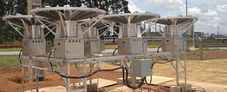
thermoelectric generators remote power system
Thermoelectric generators at remote site
Courtesy Gentherm GPT
Some operations, by their nature, dictate the location in which they will be undertaken. An obvious example is oil and gas production, but there are many others. These sometimes challenging locations burden designers and operators with providing remote communications, even on site power generation. Remote installations can often be unattended, yet require reliable continuous electric power to operate. Establishing an on site power source requires thoughtful selection of technology and equipment to provide the best solution.

thermoelectric generator is one of several solutions to consider as a power source at a remote location. Each generation technology has a set of attributes making it more or less desirable for an application under consideration.

Thermoelectric generators convert heat directly into electricity using a fuel source for heat, a hermetically sealed thermopile, cooling fins, and no moving parts. The TEG delivers a low maintenance and cost effective solution for remote power requirements, having operational and cost benefits over engine driven generators, batteries and solar sources for many applications.

The short document below provides an overview of thermoelectric generator operation and application. Talk to a product specialist about your need to power and communicate with a remote site. A thermoelectric generator may be an option you had not considered, but may prove to be the best solution.


Installing a Clamp-on Ultrasonic Flow Meter

industrial process ultrasonic flowmeter clamp on style
Ultrasonic flow meter with clamp on sensor
Courtesy Flexim
Ultrasonic flow meters are utilized throughout the fluid processing industries, as well as for compressed air and energy monitoring. The non-invasive nature of the sensor installation couples with sufficient accuracy and low maintenance requirements to give this technology a competitive edge for many applications.

Producing consistently accurate results with an ultrasonic flow meter depends heavily on a proper installation. Flexim, a globally recognized leader in the manufacture of ultrasonic flow meters, provides us with a video that steps through the installation process, with recommendations and guidance along the way.

Flexim manufactures a full range of ultrasonic flow measurement equipment and instruments for industrial and commercial applications. Share your flow measurement challenges with process measurement experts, combining your process knowledge with their product application expertise to develop effective solutions.

Monitoring Generator Sets in Standby Mode Increases Reliability

Remote Monitoring of Electric Generator in Standy Mode
Electrtic generators used as backup power sources play a critical role in maintaining operations at many facilities. They may be automatically test run periodically, but still sit idle for extended times. Continuous remote monitoring of equipment condition can reduce the risk of a failed start.

Acromag, a globally recognized manufacturer of signal conditioning equipment, has authored an application note outlining the extent of remote monitoring that should be employed and how to accomplish it.

The application note is included below. Share your process signal conditioning and transmitting challenges with product specialists, combining your process knowledge with their product application expertise to develop effective solutions.


In-Line Thermal Flow Meters

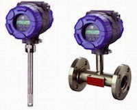
in-line thermal dispersion flow meters
In-line thermal dispersion flow meters
Thermal Instrument Company
Thermal dispersion mass flow meters provide an accurate means of mass flow measurement with no moving parts and little or no encroachment on the media flow path. There are a number of different configurations to be found among various manufacturers, but all function in basically the same manner.

Two sensors are exposed to the heat transferring effect of the flowing media. When the media composition is known, the mass flow can be calculated using the meter reading and the pipe cross sectional area. One of the flow meter sensors is heated, the other is allowed to follow the media temperature as a reference. The heat dispersion from the heated sensor is measured and used to calculate mass flow.

Some positive attributes of thermal dispersion flow meters:

  • In-line and insertion configurations available to accommodate very small to large pipe sizes
  • Rugged Construction – Stainless Steel with available protective coatings and other specialty metals
  • No moving parts
  • Measure liquid or gas in general, sanitary, and ultra pure applications
  • Measurement not adversely impacted by changes in pressure or temperature
  • Wide range of process connections 
  • In-line versions provide unobstructed flow path
  • Wide turndown suitable for extended flow range
  • Back up sensors for extended life
  • Sensors do not contact process media
  • Flow and total flow measured
  • 4-20 mA output interfaces easily with other instruments and equipment
Share all your process measurement challenges and requirements with product application specialists, combining your process knowledge with their product application expertise to develop effective solutions.

Foot Valves: Basic, Hidden, Essential

industrial valve foot valve suction valve
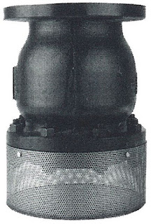
Foot valve showing inlet filter screen
Colton Industries
A foot valve is a purpose specific check valve. Designed for immersion in a well, tank, or other liquid containing vessel, it serves as a one-way inlet valve on piping leading to the suction side of a pump. Foot valves and their connected piping will extend downward from the pump suction elevation. The purpose of the valve is to maintain prime on the pump by preventing the water column in the suction line from collapsing, due to gravity, and draining all the liquid from the suction side of the pump system.

For industrial applications, there are numerous versions of foot valves available in varying sizes, capacities and materials of construction. The function of the valve is simple, so the key selection criteria can be focused on features that will contribute to longevity and reduce or eliminate any maintenance burden.

The data sheet below provides some good illustrations of a foot valve and how it is installed. Share your fluid processing and control challenges with application experts, combining your process and facility knowledge with their product application expertise to develop effective solutions.

Pneumatic Volume Booster Function

pneumatic volume booster
Pneumatic Volume Booster
Fairchild
A volume booster is used in a pneumatic control system to relay a low flow signal as one with greater flow volume. The common configuration is to provide a 1:1 ratio between the input and output pressure, keeping the input and output signals the same pressure. Products are available that deliver different ratios.

The general purpose of a volume booster is to provide a relay between a system with low flow volume and one with higher volume requirements. A typical example is a pneumatic actuator. The flow available through the pneumatic signal line may be insufficient to deliver the response rate desired from the pneumatic actuator. A volume booster, with control over an independent air supply, solves this challenge with increased flow volume at the same pressure as the control signal.

Volume boosters are simple in operation. The input signal applies force to one side of a diaphragm, the output pressure to the other. An imbalance between the two applied pressures will cause the diaphragm to move, changing the position of the valve and the outlet pressure until the two forces are again in balance. Little maintenance is required when the units are properly installed and supply air is of good quality.

The unit pictured is from Fairchild, a well recognized manufacturer of industrial pneumatic components, and provides a 1:1 ratio. There are some key points in the selection process, so reach out to a product specialist with your pneumatic system challenges and requirements. Combining your process and facility knowledge with their product application expertise will produce effective solutions.


Knowledge Base and Selection Guide For Magnetic Level Indicators

Orion Instruments Magnetic Level Indicators
Magnetic Level Indicators
Courtesy Orion Instruments
Industrial process control frequently involves the storage of liquid in vessels or tanks. Continuous and accurate indication of liquid level within the tank is an essential data point for safety and process management. While there are a number of methods and instrument types utilized to provide tank level measurement, the instrument of choice is often a magnetic level indicator, also referred to as a magnetic level gauge. Its use for providing level indication has a number of positive attributes:
  • Construction that is resistant to breakage.
  • Measuring indicators, switches, and transmitters mounted externally, without contacting the medium being measured.
  • Maintenance free operation. No regular cleaning needed.
  • Readable level indication from greater distance than glass sight gauges.
  • Magnetic level indicators can accommodate greater fluid level ranges without the need for multiple instruments.
Orion Instruments, a Magnetrol company and industry leader, has produced a comprehensive guide to magnetic level gauges, switches, transmitters, and related products. It delivers experts and newcomers an understandable and clear description of the technology and principals of operation behind magnetic level gauges and instruments. The guide also assists the reader in properly specifying and selecting the best instrument configuration for an application. A table of contents at the front of the document helps readers to quickly find the information they need.

Take a couple minutes to roll through the document and you are likely to find new and useful application tips and product information. Any questions about magnetic level indicators or your process measurement and control applications can be clearly addressed by a product specialist.


Basics of Infrared Flame Detection

flame detector
Triple IR flame detector
(courtesy if Sierra Monitor)
A flame detector is a specialized sensor used to detect and respond to the presence of a flame, and accordingly notify an operator, sound an alarm, close a fuel supply valve, shut down a pump, and turn on a fire suppression system. 

Flame detectors are fast acting and accurate, much more so than smoke or heat detectors because of the technology they employ. Some flame detectors can detect fires up to 215 feet away and be accurate enough to detect a 1 sq. foot gasoline pan at 215 feet in less than 5 seconds. 

One popular type of flame detection technology used is measuring infrared (IR) light coming from a source. This type of sensor monitors the infrared light spectrum for very specific patterns given off by hot gases. These hot gases are sensed by a specialized fire-fighting thermal imaging (thermographic) camera. 

One method of determining if a fire exists is by looking for the infrared peak of hot carbon dioxide (approximately 4.4 micrometers). Response times of a typical IR detector is 3–5 seconds. 

There is the possibility, however, of false alarms caused by background thermal radiation and other hot surfaces in the area. Another potential concern is with the formation of condensate on the flame detector's lens, which can greatly reduce its accuracy. Direct exposure to sunlight for these types of detectors can also be problematic. 

An approach to overcome these issues is with dual or triple IR sensors, which compare the threshold signal in two or three infrared ranges. Often one sensor looks at the 4.4 micrometer carbon dioxide (CO2) emission, while the other sensors looks at additional reference frequencies. Modern flame detector design allow users to select different sensitivity levels to ensure no other detectors cross-over detection zones. 

Additional important features to be considered are heated windows to eliminate condensation and icing, HART and Modbus capabilities for digital communications, low excitation power, and compact design. 

When selecting a flame detector for any application, it is important to make sure it is approved and certified for that specific use. Check for third party agency approval including FM, ATEX, IECEx, TUV, and CSA. These approvals and certifications assure the highest quality of products and performance.

Finally, the proper application of flame detectors is critical in many applications for the safety and protection of property and personnel. Therefore, it is always suggested that your application be discussed with a qualified application engineer

Steps to Installing a Rotameter

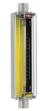
Rotameter
Rotameter


A rotameter, also known as a variable area flowmeter, is a device that measures the flow rate of liquid or gas in a closed tube. It measures flow rate by allowing the cross-sectional area the fluid travels through, to vary, causing a measurable effect. They are a cost-effective flow measuring device that provides excellent repeatability, requires no external power, can be made from a wide variety of materials, and may be designed for high pressure and high temperature applications.

The following are helpful, general guidelines in the proper installation of rotameters:
  1. Inspect meter for damage that may have occurred during shipping. Report any damage to the container to the freight carrier immediately. 
  2. Make sure your pressure, temperature, fluid and other requirements are compatible with the meter and components (including o-rings). 
  3. Select a suitable location for installation to prevent excess stress on the meter which may result from: 
    • Misaligned pipe. 
    • The weight of related plumbing. 
    • “Water Hammer” which is most likely to occur when flow is suddenly stopped as with quick closing solenoid operated valves. (If necessary, a surge chamber should be installed. This will also be useful in pressure start-up situations.) 
    • Thermal expansion of liquid in a stagnated or valve isolated system. 
    • Instantaneous pressurization which will stress the meter and could result in tube failure. note: In closed thermal transfer or cooling systems, install the meter in the cool side of the line to minimize meter expansion and contraction and possible fluid leaks at the threaded connections. 
  4. Handle the meter carefully during installation. 
    • Use an appropriate amount of teflon tape on external pipe threads before making connections. Do not use paste or stick type thread sealing products. 
    • Over tightening of plastic connections may result in fitting damage. 
  5. Install the meter vertically with the inlet port at the bottom. 
  6. Meters with stainless steel fittings will support several feet of pipe as long as significant vibration or stress resulting from misaligned pipe are not factors. 
  7. Meters with plastic fittings must be installed so that fittings are not made to support any part of the associated plumbing. In addition, meter frame should be fastened to bulkhead, panel or column. 
  8. Meters used in gas service should have suitable valves plumbed in at the inlet and outlet of the meter. These valves should be no more than 1-1/2 pipe diameters from the meter ports. The valve at the outlet should be used to create back pressure as required to prevent float bounce. It should be set initially and then left alone. The inlet valve should be used for throttling purposes. Depending on the installation, valves may not be essential, but they are most useful in many installations. Remember: To get a correct reading of flow in gas service, it is necessary to know the pressure right at the outlet of the meter (before the valve). 
  9. Pressure and temperature maximums must never be exceeded

Thermal Dispersion Flow and Level Technology

thermal dispersion instruments
Thermal dispersion level and flow
instruments (courtesy of Magnetrol)
Thermal dispersion instruments work on the basis of heat transfer. The sensing probe consists of two separate components, both RTDs (temperature detectors). One RTD is used as the reference point and measures the temperature of the fluid right where the probe is immersed. The second RTD is self-heated to a known temperature and maintained. A resulting a temperature differential is created between the two RTDs. By varying the power to the self-heated RTD, the set point can be changed which allows the user to set the instrument for a specific application.

Convective heat is the mechanism of heat transfer for thermal technology level switches based on the principle that a liquid has a thermal conductivity far greater than the thermal conductivity of its corresponding vapor. When the sensor is dry, there is a temperature difference between the two sensors. When fluid comes in contact with both RTDs, there is a cooling effect as the liquid absorbs the heat from the self-heater RTD. The resulting temperature differential drops, and creates a point for high level reference. When the level drops and the sensor goes dry, the temperature difference increases again. The instrument electronics senses the increase in temperature difference and provides a low level reference.

When used for flow applications, the temperature difference under a low flow or no flow condition is controlled by the set point. As the flow rate increases, the sensing RTD is cooled by the fluid moving past the heated sensor - the greater the flow, the greater the cooling. Conversely, the reduction in the temperature differential between the two RTDs indicates that the flow rate is exceeding the set point of the instrument.

Float Operated Level Switch Fundementals

Float Level Switch
Float Level Switch
(courtesy of Magnetrol)

Float operated level switches are suitable for use on clean liquid applications alarm, pump control and safety shutdown applications.

These float type units are typically designed, fabricated and certified to compliance with ASME B31.3 specifications.

The design of float operated level switches is based upon the principle that a magnetic field will penetrate non-magnetic materials such as 316 stainless steel. In the case of a float type level switch, the float moves a magnetic attraction sleeve within a non-magnetic enclosing tube which in turn trips an electrical switch mechanism. The enclosing tube of housing provides a pressure seal for the chamber as well as the process.

As the liquid level rises in the chamber (refer to Figure 1), the float moves the magnetic attraction sleeve up within the enclosing tube, and into the field of the switch mechanism magnet. Resultingly, the magnet is drawn in tightly to the enclosing tube causing the switch to trip, “making” or “breaking” the electrical circuit.

As the liquid level falls, the float drops and moves the attraction sleeve out of the magnetic field, releasing the switch at a predetermined “low level” (refer to Figure 2). The tension spring ensures the return of the switch in a snap action.

Measuring Flow - The Transit-Time Difference Method

transit-time difference method
Transit-time difference Method
(courtesy of FLEXIM)

The Transit-Time Difference method exploits the fact that the transmission speed of an ultrasonic signal depends on the flow velocity of the carrier medium.

Similar to a swimmer swimming against the current, an ultrasonic signal moves slower against the flow direction of the medium than when in flow direction.

The Measurement Principle

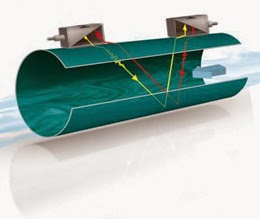
transit-time difference method
Diagram of FLEXIM transit-time
difference flow meter design.
For the measurement, two ultrasonic pulses are sent through the medium, one in the flow direction, and a second one against it. The transducers are alternatively working as an emitter and a receiver.

The transit-time of the ultrasonic signal propagating in the flow direction is shorter than the transit-time of the signal propagating against the flow direction. A transit-time difference, Δt, can thus be measured and allows the determination of the average flow velocity based on the propagation path of the ultrasonic signals.

An additional profile correction is performed by proprietary FLEXIM algorithms, to obtain an exceptional accuracy on the average flow velocity on the cross-section of the pipe - which is proportional to the volume flow.

Since ultrasounds propagate in solids, the transducers can be mounted onto the pipe.

The measurement is therefore non-intrusive, and thus no cutting or welding of pipes is required for the installation of the transducers.


Cycle Chargers - GlobalCharge Remote Power Systems by Global Thermoelectric

Cycle Chargers are the most fuel-efficient remote power system available today. They offer the highest efficiency of any prime remote power system and represent some of the toughest equipment on the market. Cycle Chargers are designed for long-term unattended operation, but can also be effective in support of grid supply. 

Global Thermoelectric, a leader in remote power systems, offers GlobalCharge - a fully self-contained remote power system offering continuous prime power from 300 Watts to 6000 Watts.

GlobalCharge is a self-contained remote power system that is ideal for applications where fuel consumption is a priority, or where only liquid fuel is available.

The technology associated with the charging system is proven as it has been used in specialized applications for over 15 years in the military, coast guard and border control. Global Thermoelectric has adapted this technology for use in industrial applications.

The result is a quiet, discreet product that operates reliably in areas where site access is difficult and site visits less frequent.


For more information contact:

M.S. Jacobs
800-348-0089
www.msjacobs.com

Magnetrol Hygienic Level Control Solutions

Here is a short video that illustrates the use of several level control technologies - guided radar level, ultrasonic level and thermal dispersion -  in hygienic applications.

The video shows us the benefits of each technology and where the Eclipse, Echotel and Thermatel controls are typically used.


For more information on level control in Western PA and West Virginia, contact MS Jacobs at 800-348-0089 or www.msjacobs.com

When to Use Pressure Gauge Accessories

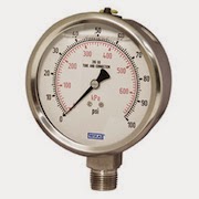
pressure gauge
Pressure Gauge (Wika)
Gauge accessories are designed to complement a pressure gauge in order to enhance and maximize its performance. Based on the application, pressure gauge accessories may never be required; however, protecting the pressure gauge from abnormal conditions is the most common reason for choosing to use a gauge accessory. Pressure spikes, temperature fluctuations and corrosion are leading causes for premature gauge failure. Your application may benefit from a gauge accessory.

Accessories for a pressure gauge may be the extra step needed for a successful, proactive, preventative maintenance program and for extending the life of pressure gauges in environments like oil and gas, petrochemical, and chemical plants. When a pressure gauge is paired with a mini-siphon, the gauge is protected from harmful steam, vapors and liquids. When a pressure gauge is paired with an overpressure protector, the gauge is protected from pressures exceeding its maximum pressure rating. When a pressure gauge is paired with a diaphragm seal, the gauge is protected from hot, viscous, contaminated or corrosive media. When a pressure gauge is paired with a snubber, the gauge is protected from pressure pulses.