Fluid Flow Control - Slurries, Entrained and Suspended Solids

Slurry, suspended solids in fluid, toxic fluid
Industrial process control can be confronted with
hazardous, corrosive, or other fluids containing
suspended solids.
Industrial process control can involve the manufacture, storage, or transport of almost any imaginable fluid. Media can range from water to concrete, hydrogen gas to steam, and anything in between or outside of those boundaries. Valves are the favored control device for regulating fluid flow and they are available in uncountable varieties, each with particular aspects making them more of less suitable for a particular media or application.

Most industrial valves consist of a body, a stem, and some form of flow obstruction which is located within the media flow path. Operation of the stem repositions the obstruction to allow or block the flow. All of these valve types have a defined sealing surface where the obstruction contacts the body. They also have additional seals where the stem penetrates the body. These design features, while providing certain functions and application advantages, also add to the operational complexity and parts count for the valve.

There is a valve type with a simple operating principle that provides superior performance when the application involves certain media characteristics. It is called a pinch valve, and here is where it excels.

  • Resistance to abrasion and corrosion from slurries or fluids containing suspended solids and the ability to provide tight shutoff around particulates
  • Media and environmental temperature range -40 deg F to +300 deg F
  • Low to moderate operating pressure
  • Flow regulating capability and tight shutoff
  • Non clogging
  • Straight through full bore design with minimal flow resistance
  • Isolation of the valve body and workings from the media
  • Low parts count, low maintenance, easy repair/replacement
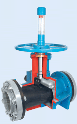
cutaway view of manually operated industrial pinch valve
Cutaway view of manually
operated industrial pinch valve
A pinch valve consists of a sleeve, through which fluid flows, and a means to compress or "pinch" the sleeve to reduce the open area inside the sleeve. The sleeves are most often fabricated from elastomers with various types of fiber reinforcement. Closure is commonly achieved through movement of one or two bars to squeeze the sleeve, providing throttling or positive closure. The flexibility of the sleeve material allows for tight shutoff, even with fluids containing suspended solids. The valves can be coupled with electric or pneumatic actuators and are available with industry standard connections. One valve variant has a body that can be pressurized to close the sleeve, without the need for a separate actuator. Pinch valves are available with and without an enclosing body.

You should be familiar with the capabilities and forms of this unique valve type. When confronted with certain application challenges, a pinch valve can be a superior solution. I included a product line data sheet from one manufacturer, General Rubber Corporation, so you can see all the different variants that are available. You can get even more information, or start a conversation about any of your process control challenges, by contacting a product specialist.


Process Measurement and Control: When To Use a Diaphragm Seal

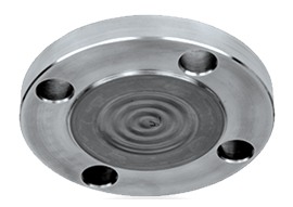
Industrial diaphragm seal for pressure measurement instrument
Diaphragm seal for pressure measurement device
Courtesy Wika
Process measurement sensors are not indestructible. Not even the most rugged device is fully immune to the chemical nature of process media or the kinetic impact associated with fluid composition and movement. Balancing degrees of protection, usually to increase the useful life of the device, with sensor response and accuracy is a frequent challenge in the process measurement and control field. 

Industrial processes commonly are associated with corrosive or toxic fluids, often at extreme pressure or temperature and containing various levels of solids. Any of these traits can pose substantial risk to process performance and uptime. Operations that process fluids will employ pressure measurement devices to monitor process performance and maintain system safety levels. There are many instances where characteristics of the process and its media are not compatible with pressure measurement devices. Here are some potentially problematic scenarios for pressure measurement instruments: 
  • Corrosive media that will prematurely deteriorate the pressure sensing element. 
  • Viscous or fibrous media, also those that may crystallize or polymerize, posing a risk of clogging channels, tubes, and orifices of pressure measurement devices. 
  • Media temperature that is beyond the rated range for the pressure measurement device has a potential to damage the instrument or cause error in the pressure reading. 
  • A measuring point that is remotely located from where a technician may need to observe the reading. Also conceivable, the pressure measurement device needs to be located away from other potentially damaging environmental conditions. 
  • The process requirements dictate specific hygienic requirements that are cause for the measurement device to be isolated from the medium. 
  • Toxic or otherwise hazardous media that must be contained. 
  • Excursions of system pressure may exceed the acceptable range of the instrument, potentially damaging the device. 
industrial process threaded diaphragm seal
Threaded diaphragm seal
Courtesy Wika
A solution which can provide protection from the items listed above, while still maintaining instrument response and accuracy is a diaphragm seal. Seals are placed between the pressure measurement device and the process media. The space between the diaphragm, which is flexible, and the sensor is filled with a fluid that will hydraulically transfer the pressure condition on the process side of the diaphragm to the sensor. The diaphragm serves as a physical barrier between the potentially damaging media and the instrument. Diaphragm seals are available in a wide variety of configurations to accommodate any media type or connection requirement.

Seal selection involves specifying the connections and form factor to properly mate the diaphragm with the instrument and the process, then selecting the diaphragm material that will be compatible with the media. The best way to achieve a positive solution is to share your requirements with a qualified assembler. They can help select the right diaphragm seal and mate it up with a pressure gauge, providing a complete assembly that is ready to be installed in your process.

Innovations In RTD Signal Conditioning - One Manufacturer's Compilation

Industrial process measurement and control RTD signal conditioner
RTD Signal Conditioning Units
Courtesy Acromag
Temperature measurement may be one of the oldest components of process control and laboratory research. The measurement of temperature has progressed through a variety of methodologies, some of which are still in use today. Modern industrial process control relies heavily on the use of RTDs (resistance temperature detector) for their accuracy and stability.

Some of us have used RTDs in our process designs for many years, maybe without recognizing the innovations that have come about in the signal conditioning portion of our installations. One manufacturer of industrial signal conditioning equipment, Acromag, has compiled the ten most significant recent advances in RTD signal conditioning. I have included their white paper below.

Browse the paper, as it is brief and informative. You will likely see a few improvements of which you were unaware. Share your temperature measurement and signal conditioning challenges with an application specialist. Combining your process experience with their product application expertise will produce positive solutions.


Ethernet I/O Modules Provide Connectivity Advantages

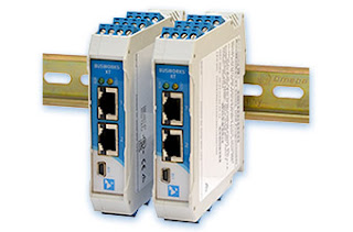
Industrial Ethernet Input and Output Modules on DIN Rail
Industrial Ethernet I/O Modules
Courtesy Acromag
Industrial process control relies on the accurate and timely delivery of process measurements and data to the point of control and decision making. As technology affords more opportunities to measure and transmit process variables, the demand for incorporating the additional information in the control and decision making process expands. The frequency at which data can flow from a process has also increased dramatically, and there is often significant value derived from rapid sampling. Transmitting the voluminous measurement data to the point of control can be accomplished using three basic methods:

  • Point to point wiring from each measurement device to the control point.
  • Wireless linkup from measurement location to controller.
  • Wired network connection between measurement and control devices.
Each of these connection topologies has particular attributes which may better suit a particular application.  For a wired network scheme, Acromag has designed a line of I/O modules that make installation and configuration a smooth operation. Helpful features include:
  • Power wiring options that allow back connected bus power or top mounted screw terminals. You can even provide primary and backup power sources to the two connections.
  • Front facing screw terminals for connections make status checking of inputs a simple operation with your digital volt meter.
  • Modules are rail mounted and can be placed immediately adjacent to one another for high density installation.
  • Modules have a built in webpage for display of operational information. Configuration is accomplished using a front mounted USB port.
  • Operable in temperatures -40 to +70 deg. Celsius.
  • Two Ethernet ports on each unit allow modules to be daisy chained, reducing or negating need for local hubs.
  • Acromag's Priority Channel Technology assures that data update frequencies are maintained, regardless of other network traffic.
The short video below provides additional detail on the useful features of the Acromag line of industrial Ethernet I/O modules. Watch the video. Share your process measurement and control connectivity challenges with a sales engineer specializing in industrial Ethernet I/O. Combine your process knowledge with the state of the art product knowledge of a product specialist for the best solutions.


Flexible Hazardous Gas Detection Monitoring System

Hazardous gas detection monitoring unit
Sentry IT Controller For Hazardous Gas Detection Monitoring
Courtesy Sierra Monitor
Industrial processes, by their scale and nature, are rife with hazards. As a process designer, engineer, or operator, protection of the facility, employees, and surrounding community ranks highest among our many responsibilities. Some hazards are apparent, visible, easily detected. Others are not. Technology and ingenuity play a substantial role in providing acceptable levels of safety in modern facilities.

Properly designing a hazardous gas monitoring system starts with identifying the target elements and their sources. Gaseous hazards can generally be divided into three general classes, all of which can be specifically targeted with a properly configured gas monitoring system.


  • Combustible gas concentrations subject to ignition and explosion.
  • Toxic gas with inherent personnel risk.
  • Insufficient oxygen levels to support human respiration.

The best overall system configuration can be achieved through a combination of detectors, communications, and response that will provide accurate sensing of the target hazard, reliable and predictable transmission of information, and preconfigured response when alarm limits are triggered. Some product features for the detector monitor that may prove useful in a well specified installation:

  • A means to non-intrusively calibrate all sensors at the same time
  • Ability to diagnostically monitor connected sensors for performance.
  • Provision of an easily operable interface for users.
  • Battery backup to maintain operation during a power outage.
  • Network and protocol compatibility with a range of industry accepted standards.
  • Simple means to upgrade operating software.
  • Compatibility with detection devices from a broad array of sources.
  • Input capacity for more sensors than your current requirement.
I have included a bulletin describing such a unit, manufactured by Sierra Monitor. Browse the document and contact a hazardous gas detection application specialist to get more details and discuss your hazardous gas detection challenges. The best solutions come from combining your process knowledge and experience with that of a product application specialist.


Industrial I/O Applications Compilation Provides Answers

Process Measurement and Control Input and Output Devices
Process Measurement and Control I/O Devices
Courtesy Acromag
Process measurement always presents two basic challenges, derive a measured value of the process condition, then transmit or deliver that value to a recording or decision making device. Your knowledge and ingenuity applied to the design and implementation of these measurement and transmission functions are the key to how effectively your control system will function. Acromag, a world class manufacturer of signal conditioning equipment and industrial I/O devices, has produced a compilation of applications that illustrate some creative and best practices for establishing effective connections between control and measurement devices. The applications are drawn from defense, power generation, and manufacturing, but the knowledge shared can be broadly applied to many industries.

Look through the applications and you will find something of value. You can always contact a product and application specialist to discuss your process measurement and control challenges and requirements. Combining their product application expertise with your process knowledge will generate the best solutions.


Rotameters For Flow Measurement - Selecting the Right One

Industrial rotameter flow meters
Industrial Rotameter Flow Meters
Courtesy King Instrument
Applied extensively in industrial process measurement and control, a rotameter is an instrument that uses a float of given density to establish, for any measurable flow rate, an equilibrium position within the fluid stream where the force of the flowing fluid equals the force of gravity. Let's break that down a little. A rotameter has a tapered tube with a float inside. As the measured fluid flows upward through the tube, it pushes the float upward along the length of the tube. As the float rises in the tube, the cross sectional area of the tube increases and more fluid can bypass around the float. At some point, the upward force of the fluid flow acting on the float will balance with the downward force of gravity. The position of the float along the length of the tube correlates with a certain flow rate when certain properties of the fluid are known. Flow rate scale graduations on the tube can be read by the operator.

Rotameters are very specific to each flow measurement application. It's important that you know your fluid properties, ambient conditions, connection and readability specifications. 

Start with these selection parameters:

  • Desired flow rate range
  • Fluid specific gravity
  • Ambient temperature
  • Operating and maximum pressure
  • Line size
  • Connection type
  • Connection orientation
  • With or without a valve
  • Material requirements to accommodate fluid
  • Scale units of measure. Smallest scale divisions needed.
For each application, it's advisable to work closely with a sales engineer to gather all the needed information and coordinate the product selection process.

Here are some things to consider for potential rotameter applications:


  • Simple design and operation provide a modest cost solution.
  • No external power is required for operation. Inherent fluid properties and gravity are used to measure flow rate.
  • Clear glass used for the measuring tube is highly resistant to thermal shock and corrosion.
  • Instrument orientation must be vertical, with fluid flowing upward.
  • Scale graduations are accurate for a given substance at a given temperature, making the devices application specific.
  • Operation of the rotameter may be impacted by changes in the viscosity of the fluid. Consult with a product and application specialist to explore your application.
  • Direct flow indication provides resolution that may not be as good as some other flow measurement methods.
  • Visual reading of the scale is subject to uncertainty due to float oscillation, parallax, and location on the scale.
  • Make sure the fluid turbidity, or another fluid characteristic will not obscure the visibility of the float.

Consult with a product specialist about your flow measurement application. A combination of your process knowledge and their product expertise will produce the best solution.


Analynk Wireless Updated Website

Analynk Wireless company logo
Analynk Wireless has a new website
One of the manufacturers represented by MS Jacobs & Associates, Analynk Wireless, has redesigned and published an updated website. The new site provides access to features, model configurations and datasheets for their entire range of industrial process control and measurement products. Analynk's product line complements those of other manufacturers in the MS Jacobs portfolio of industrial instrumentation and process control products. MSJ employs the Analynk products, often in combination with products of their other manufacturer lines, to provide complete packaged process control solutions for their customers.

Analynk Wireless encompasses three groups of products:

  • Hazalynk® wireless products for hazardous areas, including explosion proof antennas and hazardous area access point enclosures.
  • Sensalynk® single and multi-point wireless transmitters, receivers, and repeaters for industrial wireless networking.
  • Telmar® transmitters, tachometers, signal alarms, power supplies, indicators and meters for process measurement and control.
Take a look at the new Analynk website. Discuss your process improvement ideas with product application specialists and develop a plan to generate better outcomes.

Application Suitability of Ultrasonic Flowmeters

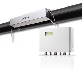
Ultrasonic Liquid Flow Meter
Ultrasonic Liquid Flow Measurement System
Courtesy Flexim America
Industrial process control frequently requires the accurate measurement of fluid flow. There are several widely applied methods for measuring flow, each having particular advantages which may apply to a specific application.

Ultrasonic flow meters measure flow indirectly by calculating transit time of a sound wave through, or reflecting from, a flowing fluid. The velocity of the fluid has an impact on the transit time, from which a flow rate can be calculated. Attributes of ultrasonic flow measurement that may determine suitability for a particular application include:

  • Transducers can be clamped on exterior pipe surface where measurement is needed.
  • Non intrusive measurement technology prevents contact between media and measuring elements.
  • No significant pressure drop associated with measuring device installation.
  • Reduced leak potential.
  • No moving parts.
  • Comparatively higher cost than some other technologies.
  • Fluid characteristics must be well known for proper application.
  • Pipe cross section must be completely filled by media to acquire accurate flow measurement.
Learn more about this process measurement and control technology in the product detail sheet below. Consult with a product application specialist for more detailed product information and tips on how to best apply ultrasonic flow meters to your process.