Thermal Mass Flow Measurement of Tank Blanketing Gas

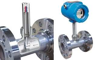
thermal dispersion mass flow meter insertion type
Insertion style thermal mass flow meter can measure
low flow rates of gas for tank blanketing.
Courtesy Magnetrol
Closed liquid tanks and other vessels contain two substances, liquid and not liquid. The liquid, in this case, is the subject material of a process. The "not liquid" is whatever fills the space not filled by the subject liquid. There are many cases where the process, the subject liquid, and safety are best served by filling the space with a known gas. There may be concerns about ignition of the vapor from the liquid, reactivity of the liquid with oxygen, or a wide range of other issues that call for filling the tank space with a known gas.

Nitrogen is a commonly employed gas for tank blanketing. It is comparatively inexpensive and widely available. It can inhibit combustion by displacing atmospheric oxygen and is not reactive with most industrial process chemicals.

Vessels with rapidly changing levels, or those of very large size, will require larger available flow capacity of blanketing gas to maintain the desired conditions within the tank. There are regulating valves designed specifically for tank blanketing operations. Vents intended for use in the same application are also commercially available.

Monitoring tank liquid level and gas flow are part of best practices for a tank blanketing operation. Confirming that gas flow rate is commensurate with the requirements for current tank level confirms proper operation. Too high a flow rate could indicate a leak or malfunction of a blanketing system component. It may also be useful to totalize gas flow for use in operational planning.

Thermal insertion flow meters are suitable for measuring the wide range of gas flow rates employed in tank blanketing applications. The instruments are available for insertion installation, as shown in the image near the top of this article, or as inline units. Either configuration delivers accurate measurement with no moving parts, a high turndown ratio, and minimal maintenance requirement.

Share your tank blanketing requirements and challenges with process measurement and control specialists, combining your own process knowledge and experience with their product appliction expertise to develop effective solutions.

Thermal Mass Flow Meter Questions Answered by Experts

Insertion style thermal mass flowmeter
Thermatel, insertion style thermal mass flow meter
Image courtesy of Magnetrol
Knowledgeable individuals that share expertise and experience with others in their field are a valuable resource, worthy of our attention.

Tom Kemme, from Magnetrol®, expertly fielded some questions about thermal mass flow meters in a recent blog post. Mr. Kemme's responses were so useful and clear that I decided, with all the credit flowing his way, to share them here for those of you that may not closely follow the Magnetrol® Blog.

Will thermal mass flow meters be affected by changes in the composition of gas (i.e. will they require recalibration every time the composition changes)?
Thermal mass flow meters measure a flow rate based on convective heat transfer. Fluid properties are some of the many factors that influence convection. Each gas has unique properties, which is why these flow meters are calibrated for a specific application. You would not want a meter calibrated for an air application placed into a natural gas application without recalibration or some type of field adjustment if applicable.
All gas mixes are not created equal. If you had a gas mix with high hydrogen content, a variation in hydrogen would have a much greater effect than typical variation in natural gas content. Hydrogen has a tendency to create more heat transfer than most gases. For natural gas, it is common to have some slight variation in composition between the calibration of the device and the application itself. However, the effect is minimal for slight changes in methane or ethane at different times of the year. Natural gas fuel flow is one of the most prevalent applications for thermal mass.
Based on our experience, the biggest cause of malfunction in flow meters is improper installation. If you do not install a flow meter per the manufacturer’s recommendation this will greatly influence the performance of the meter. For thermal mass, this includes proper straight run, depth into the pipe (insertion probes) and flow arrow alignment.
Each application presents unique difficulties for every flow meter technology, and each end user has unique needs. There is no exact answer as to when a recalibration would be needed for thermal mass flow, as it is application dependent. You do not always need recalibrations for variation in gas composition.
What role do thermal flow meters play in emissions monitoring applications?
Thermal flow meters are at the forefront in flow measurement for emissions reporting and energy management projects. The energy management arena spans many markets, including some of the largest in the oil & gas and power industries. Some popular applications include monitoring gas fuel flow to a combustion source to report SO2 (sulfur dioxide) emissions, stack (flue) gas flow in power plants as part of a continuous emissions monitoring (CEM) system of NOX (nitrous oxide) and SO2, and flares in a gas field that need to be reported to environmental authorities. These applications prove difficult for many flow meter technologies.
For example, in a flare application most of the time gas is not being flared off, but it needs to be measured in case of an event. The user will want to monitor the low flow of pilot gas keeping the flare lit. This requires a flow meter with a very high turndown with good low flow sensitivity, which is a limitation of some technologies, such as differential pressure flow meters.
Many operators are most concerned with measuring CO2 (carbon dioxide) emissions. However, with thermal flow meters we are increasingly finding applications with the need for methane measurement. Methane is a greenhouse gas that has more than 20 times the global warming potential as CO2. No longer can coalmines or landfills emit this directly to the atmosphere. If not flaring the gas off, the owners are beginning to capture it, treat it, and produce usable natural gas from it. Some facilities that emit landfill gas, or facilities that produce biogas, are involved in carbon credit programs or clean development mechanisms. Similar applications can be found in wastewater treatment plants where customers are reporting digester gas emissions and even capturing this gas to produce electricity and reduce energy costs. Thermal dispersion flow meter technology, such as the MAGNETROL Thermatel® TA2, has become well accepted in all of these markets.
You can easily tap into Magnetrol® expertise to solve your flow measurement challenges. Reach out to a product specialist and combine your process knowledge with their flow measurement expertise to develop effective solutions.

Thermal Dispersion Flow Switches For Pump Protection

thermal dispersion flow switch pump protection
Thermal dispersion flow switches have advantages
when applied for pump protection
Image courtesy Magnetrol
Good practice for installing industrial pumps calls for inclusion of protective devices to assure that the pump is not exposed to conditions beyond its design intent. Monitoring liquid flow is a useful method for determining if a pump is operating within a safe range.

There are numerous methods of verifying flow in piping connected to a  pump. Magnetrol, globally recognized manufacturer of flow and level measurement technologies, offers up their assessment of various pump protection measures and a recommendation for what they consider an advantageous choice for flow measurement in a pump protection application.

Magentrol's white paper is included below, and you can share your flow and level measurement challenges with application experts for help in developing effective solutions.


Corrosion Resistant Flow Meter


There are numerous flow measurement technologies available for application in process measurement. Each technology is represented by a broad array of product variants, each with a set of attributes making it suitable for certain applications.

ICON Process Controls specializes in corrosion resistant industrial fluid handling and process control equipment, offering the most complete line of all plastic instrumentation products supported by the largest inventory in North America. Applications for their corrosion resistant instruments include Municipal and Industrial Water & Wastewater Treatment, Bulk Chemicals, Steel Processing, Metal Finishing, Chemical Dosing Skids, Food & Beverage.

Share your process measurement and control requirements with instrumentation specialists. Combine your own knowledge and experience with their product application expertise for effective solutions.

Hydrostatic Pressure Measurement for Determining Liquid Level

pressure transmitter for mounting to flange on a tank
Pressure transmitters can be used to provide liquid level in
pressurized or open vessels.
Photo courtesy Azbil North America
Pressure measurement is an inferential way to determine the height of a column of liquid in a vessel in process control. The vertical height of the fluid is directly proportional to the pressure at the bottom of the column, meaning the amount of pressure at the bottom of the column, due to gravity, relies on a constant to indicate a measurement. Regardless of whether the vessel is shaped like a funnel, a tube, a rectangle, or a concave polygon, the relationship between the height of the column and the accumulated fluid pressure is constant. Weight density depends on the liquid being measured, but the same method is used to determine the pressure. 

A common method for measuring hydrostatic pressure is a simple gauge. The gauge is installed at the bottom of a vessel containing a column of liquid and returns a measurement in force per unit area units, such as PSI. Gauges can also be calibrated to return measurement in units representing the height of liquid since the linear relationship between the liquid height and the pressure. The particular density of a liquid allows for a calculation of specific gravity, which expresses how dense the liquid is when compared to water. Calculating the level or depth of a column of milk in a food and beverage industry storage vessel requires the hydrostatic pressure and the density of the milk. With these values, along with some constants, the depth of the liquid can be calculated.

The liquid depth measurement can be combined with known dimensions of the holding vessel to calculate the volume of liquid in the container. One measurement is made and combined with a host of constants to determine liquid volume. The density of the liquid must be constant in order for this method to be effective. Density variation would render the hydrostatic pressure measurement unreliable, so the method is best applied to operations where the liquid density is known and constant.

Interestingly, changes in liquid density will have no effect on measurement of liquid mass as opposed to volume as long as the area of the vessel being used to store the liquid remains constant. If a liquid inside a vessel that’s partially full were to experience a temperature increase, resulting in an expansion of volume with correspondingly lower density, the transmitter will be able to still calculate the exact mass of the liquid since the increase in the physical amount of liquid is proportional to a decrease in the liquid’s density. The intersecting relationships between the process variables in hydrostatic pressure measurement demonstrate both the flexibility of process instrumentation and how consistently reliable measurements depend on a number of process related factors. 

Share your process measurement and instrumentation requirements and challenges with professionals that specialize in their proper selection and application. Combining your own process knowledge and experience with their product application expertise will help to develop effective solutions.

Commercial and Industrial Process Heating Methods

Special design electric heating element
Electric heating element of special design
Many industrial processes involve the use of heat as a means of increasing the energy content of a process or material. The means used for producing and delivering process heat can be grouped into four general categories.
  • Steam
  • Fuel
  • Electric
  • Hybrid
The technologies rely upon conduction, convection, or radiative heat transfer mechanisms, solely or in combination, to deliver heat to a substance. In practice, lower temperature processes tend to use conduction or convection. Operations employing very high temperature rely primarily on radiative heat transfer. Let's look at each of the four heating methods.

STEAM

Steam based heating systems introduce steam to the process either directly by injection, or indirectly through a heat transfer device. Large quantities of latent heat from steam can be transferred efficiently at a constant temperature, useful for many process heating applications. Steam based systems are predominantly for applications requiring a heat source at or below about 400°F and when low-cost fuel or byproducts for use in generating the steam are accessible. Cogeneration systems (the generation of electric power and useful waste heat in a single process) often use steam as the means to produce electric power and provide heat for additional uses. While steam serves as the medium by which heat energy is moved and delivered to a process or other usage, the actual energy source for the boiler that produces the steam can be one of several fuels, or even electricity.

FUEL

Fuel based process heating systems, through combustion of solid, liquid, or gaseous fuels, produce heat that can be transferred directly or indirectly to a process. Hot combustion gases are either placed in direct contact with the material (direct heating via convection) or routed through tubes or panels that deliver radiant heat and keep combustion gases separate from the material (indirect heating). Examples of fuel-based process heating equipment include furnaces, ovens, red heaters, kilns, melters, and high-temperature generators. The boilers producing steam that was described in the previous section are also an example of a fuel based process heating application.

ELECTRIC

Electric process heating systems also transform materials through direct and indirect means. Electric current can be applied directly to suitable materials, with the electrical resistance of the target material causing it to heat as current flows. Alternatively, high-frequency energy can be inductively coupled to some materials, resulting in indirect heating. Electric based process heating systems are used for heating, drying, curing, melting, and forming. Examples of electrically based process heating technologies include electric arc furnace technology, infrared radiation, induction heating, radio frequency drying, laser heating, and microwave processing.

HYBRID

Hybrid process heating systems utilize a combination of process heating technologies based on different energy sources or heating principles, with a design goal of optimizing energy performance and overall thermal efficiency. For example, a hybrid steam boiler may combine a fuel based boiler with an electric boiler to take advantage of access to low off-peak electricity cost. In an example of a hybrid drying system, electromagnetic energy (e.g., microwave or radio frequency) may be combined with convective hot air to accelerate drying processes; selectively targeting moisture with the penetrating electromagnetic energy can improve the speed, efficiency, and product quality as compared to a drying process based solely on convection, which can be rate limited by the thermal conductivity of the material. Optimizing the heat transfer mechanisms in hybrid systems offers a significant opportunity to reduce energy consumption, increase speed and throughput, and improve product quality.

Many heating applications, depending on scale, available energy source, and other factors may be served using one or more of the means described here. Determining the best heating method and implementation is a key element to a successful project. M.S. Jacobs and Associates specialize in electric heating applications and facets of the industrial production of steam. Share your process and project challenges with them and combine your facilities and process knowledge and experience with their product application expertise to develop effective solutions.

Wireless Communications Deliver Real Time Process Data From Remote Operating Sites

Oil is where you find it, with many prospecting and production sites located where the communication options taken for granted in developed areas do not exist. Oil is big and serious business, with tremendous sums of money at risk on the prospect of reaping even greater returns. Every business operation, though, is of great importance to the stakeholders. Countless operations in little known industries and endeavors are located beyond the boundaries of modern communications infrastructure.
If you want a data connection, bring your own.
Remote operating sites, whether for oil extraction or other purposes, will often be automated. Some decision making system or individual is responsible for the safe and effective operation of the remote site, or has a use or need for real time data being gathered at the remote site. Radio transmission is a viable, maybe the best, option for delivering real time data from a remote site to a central office.
  • Transmission options for 900 MHz, 2.4 GHz, cellular, and satellite systems are readily available.
  • Equipment operates on low voltage, low power. Suitable for solar or other remote site power source.
  • No special instrumentation needed. Radio transmitting and receiving equipment interfaces directly with analog signals from common industrial process transmitters.
  • No "across the land" cabling needed.
  • Equipment can be configured to resist extreme environmental conditions.
Analynk manufactures transmission and receiving equipment that builds the bridge between remote sites and the home office. From elemental componentry to integrated, ready to run systems, Analynk specializes in wireless communications for industrial process control. Share your wireless process data connection challenges with process measurement and control specialists. Whether an expansive multipoint, or a single point application, application specialists can combine standard or customized products into a practical solution for every application.

Zero Bleed Pneumatic Controller for Valve Actuators and Other Process Control Apps


This video shows the components of the BiFold Zero Bleed Pneumatic controller. Called "PICO", this unit was first described in a previous article. Check out the video, as it nicely lays out the various operating components of a complete system. More information is available from product application specialists, with whom you should share your valve control and actuation challenges to get positive and effective solutions.

Zero Bleed Pneumatic Controller

zero bleed pneumatic positional control
The PICO consists of a single logic control head
and a digital filter booster
Courtesy Bifold - Rotork
The Bifold brand, under the Rotork corporate umbrella, developed a true zero bleed pneumatic position controller for valve actuators. The product, called PICO, consists of a single logic control head and a digital filter booster. The control head unit provides bluetooth communications, ESD monitoring and control, graphic display, integral valve feedback measurement, low power modes, a partial stroke test feature and local control setting switch. The properly installed assembly is suitable for use in hazardous locations.

The new control unit is capable of fulfilling applications employing positional control, on/off and ESD (emergency shutdown) valves. The filter booster allows the small size of the PICO to deliver the flow rate of a substantially larger system of conventional design.
pneumatically actuated control valve with zero bleed controller
The PICO, with control head and filter booster
shown installed on pneumatically actuated valve
Courtesy Rotork - Bifold

The PICO provides a number of operational benefits to pneumatic actuated valve applications. More information is available from product application specialists, with whom you should share your valve control and actuation challenges to get positive and effective solutions.


Two New Products From SVF Flow Controls

rack and pinion actuator and butterfly valves
New products from SVF Flow Controls
SVF Flow Controls, manufacturer of valves and actuators for industrial process control (learn more here), recently released their new rack and pinion actuator, the EZ-Tork™. The line of pneumatic valve actuators features bi-directional stroke adjustment, a continuous position indicator, hard anodized aluminum housing, and universal mounting. The line offers 33 models spanning a broad range of operating torque. Units are available in double acting or spring return variants.

The SL Series of butterfly valves feature direct mounting for electric or pneumatic automation. Manually operated units have a ten position locking handle or gear operator. Epoxy coated ductile iron body, 316 stainless steel disc, and EPDM or BUNA seats enable the application of this valve throughout many industrial settings. Sizes range from 2" to 12".

More detail is available from valve and fluid control specialists. Share your application challenges and combine your own process knowledge with their product application expertise to develop effective solutions.

Prevent Condensation in Your Facility

condensation on glass with ice cubes
Condensation can have a negative impact in
plants, buildings and other and facilities
Condensation, the accumulation of liquid water on a surface through contact with humid air, can be harmless in some settings, an undesirable or even damaging occurrence in others. In situations where condensation is undesirable, taking steps to prevent the conditions that preclude its formation are relatively simple and deliver a good payback.

What is condensation? In general usage, the term refers to the formation of liquid water droplets that occurs when humid air contacts a cooler surface. It is the liquid moisture that accumulates on the exterior of a glass containing a cold drink. Properly, the term condensation names the process of a vapor changing to a liquid. It is the opposite of evaporation. Condensate (note the different word form) is the liquid accumulated through the condensation process. This article is limited to condensate that forms when atmospheric air contacts a cold surface, so the general usage term condensation will be used.

Where can it happen? Water vapor is contained in air when it has sufficient energy to remain in the vaporous state. Remove some of that heat energy and a calculable quantity of the water vapor will no longer be supported, condensing into liquid water. The temperature at which any given quantity of air will start to shed some of its water vapor content is primarily determined by the concentration of water vapor in the air. A higher water vapor content will result in a higher temperature at which the water vapor will begin to condense. In everyday terms, higher relative humidity leads to a higher temperature at which condensation takes place.

What is the range of impact? Condensation appears to us as water that almost magically manifests on a surface. It seems to come right out of thin air.....because that is where it came from. It can form locally or broadly throughout an area. The potential impact of condensation arises from the fact that it is liquid water. Anything that will be damaged by water will be adversely impacted by condensate formation on its surface. This includes rust and corrosion of metals, spotting on material or  object surfaces, the promotion of mold and mildew, and a wide range of other undesirable effects. Accumulated condensate on overhead objects or surfaces can eventually drip onto equipment, materials, and work areas situated below. Puddles of water on a floor can also create a hazard.

Prevention is the best, maybe the only cure.

How to prevent condensate formation?
  • Ventilation - If there is a source of moisture in a space that is elevating the humidity, continually diluting the space moisture content by introducing fresh air with a lower moisture content may be an effective prevention method. Ventilation relies on the fresh air conditions always being sufficient for moisture reduction without creating some other adverse impact on the space. For example, ventilating with outdoor air may be effective throughout only part of the year. Without a reliable source of ventilation air with known conditions, this method may not always deliver the desired results. Ventilation is an active method that requires energy to move the ventilation air. Additional energy may be required to adjust the temperature or moisture conditions of the ventilation air, as well.
  • Insulation - The surfaces where condensation occurs can be isolated from the moist air by insulating materials. This is common with HVAC ductwork and process piping. If done properly, this method is effective. The goal is to create a new surface that does not exhibit the cooler temperatures of the isolated surface. The thickness and reduced thermal conductivity of the insulation material will achieve this. There is also a vapor barrier on the exterior of the insulation that prevents entry of moisture laden air into the insulation material. It is important the the vapor barrier installed as part of the insulating process remain intact and undamaged. Otherwise, water vapor will enter the insulating material and condense, with the potential for a localized failure of the insulating scheme. Insulation is a passive measure that requires no added energy to remain effective.
  • Dehumidification - Outright reduction of moisture contained in the air of an enclosed space will reduce the temperature at which water vapor condenses. Dehumidification machinery is available in a wide range of sizes and performance levels to suit almost any scenario. Though it requires energy to operate, the machinery is generally simple and operates automatically to maintain a space condition that will not support condensation.
  • Heating - Some cases can be most effectively treated using the application of a small amount of heat to the surface where condensation forms. This active method can be very effective when the need is localized. Also, surface heaters can be fabricated that will fit where insulation will not, and the heating assemblies may be more resistant to impact and damage than insulating materials. Proper control of heating equipment will minimize energy consumption.
Implementing an effective plan to combat condensation involves the identification of the conditions that promote its formation in your own facility. Selecting the best prevention plan calls for consideration of costs and reliability of various schemes. Active methods, such as heating or dehumidification, have some capacity for adjustment if conditions change over time. Insulation plans should have sufficient headroom or safety factor in their design to accommodate unforeseen conditions.

Reach out to product application specialists and share your challenges and concerns. Combining your own facilities and process knowledge with their product application expertise will result in effective solutions.

M.S. Jacobs Expands Valve Product Line

Alcon industrial solenoid valves
Courtesy Rotork Instruments
M.S. Jacobs recently broadened the company's offering of solenoid valves for industrial use. The addition of the Alcon brand line, part of the Rotork Instruments Group, adds solenoid valve products suited for severe conditions and extreme temperatures often encountered in industrial settings. M.S. Jacobs has a full range of solenoid valves for general and special purpose applications, including air, water, steam, cryogenic gases and liquids, oil and fuel, corrosive media and vacuum.

More information is available. Share your fluid process control challenges with product application specialists and make the latest available product information part of your solution.

New Non-Contact Radar Level Transmitter From Magnetrol

non contact radar level transmitter
New Pulsar R86
Non-contact radar level
transmitter
Courtesy Magnetrol
The determination of level in tanks or other vessels is a lifeblood operation in fluid processing. A number of technologies are available that provide workable solutions for a designated range of uses. Selecting the most appropriate measurement technology for an application can entail consideration of how several goals are achieved.

Accuracy - Differing applications will place their own importance on the degree of accuracy needed. Some operations, depending upon the value of the material, safety impact of over or under filling, and other operation specific factors, will benefit from higher levels of accuracy. Matching the instrument accuracy to the needs of the operation can often save first cost and widen the field of prospective instruments to be considered.

Reliability - Reliability has two facets. Of course, any operation benefits from an instrument that starts working and keeps working. The challenge is to evaluate how the instrument works and compare that to how the process works. Does the process expose the instrument to conditions that may impair its function or shorten its useful life? The second facet concerns the degree of confidence that the operator can place on the level reading delivered by the instrument. Will the readings be accurate under all reasonably probable operating conditions? Are there process conditions which may generate a false level reading? The ability of the measurement technology and the instrument to consistently deliver information that can be used for decision making is paramount.

Low maintenance burden - Maintenance is still largely accomplished by people, a limited resource in any operation. An instrument that requires less technician time to maintain proper operation brings a benefit to the operation.

There can certainly be other factors to consider for any application, but a systematic weighing of those many factors can result in making a solid decision that delivers a positive outcome.

Magnetrol, globally recognized innovator in level measurement technology, has released its Pulsar R86 non-contact level transmitter for industrial process control use. The new instrument combines the company's many years of innovation in the level measurement field into a single transmitter. The unit has applications throughout almost every industry, with a powerful array of operating features.

A product datasheet is included below, so you can learn more about the Pulsar R86. Share and discuss your level measurement requirements and challenges with process measurement specialists. Combining your own process knowledge and experience with their product application expertise will produce an effective solution.


In-Line Process Refractometer


Refractometry, a combination of physics, materials, and chemistry, is a measurement technique which determines the composition of known substances by means of calculating their respective refractive indexes (RI). RIs are evaluated via a refractometer, a device which measures the curve, or refraction, resulting when the wavelength of light moves from the air into and through a tested substance. The unitless number given by the refractometer, usually between 1.3000 and 1.7000, is the refractive index. The composition of the substance is then determined with a comparison of the measured RI to standard curves developed for the substance. There are four general types of refractometers: digital, analog, lab, and inline process. Although refractometry can measure a variety of substances, the most common group of known substances to calculate is liquids. Liquid based continuous processes benefit from the use of an inline process refractometer to provide real time data about process output or intermediate steps.

The ultimate focus of industrial refractometry is to describe what is in a final product or output of a process step. A field which relies directly on the results of refractometry is gemology. Gemological refractometry is crucial for accurately identifying the gemstones being classified, whether the gemstones are opaque, transparent, or translucent.

Other common examples of industrial refractometry uses include measuring the salinity of water to determine drinkability; figuring beverage ratios of sugar content versus other sweeteners or water; setting eye-glass prescriptions; understanding the hydrocarbon content of motor fuels; totaling plasma protein in blood samples; and quantifying the concentration of maple syrup. Regarding fuels, refractometry scrutinizes the possible output of energy and conductivity, and for drug-testing purposes, refractometry measures the specific gravity, or the density, of human urine. Regarding food, refractometry has the ability to measure the glucose in fruit during the fermentation process. Because of this, those in food processing can know when fruit is at peak ripeness and, in turn, also understand the most advantageous point in the fruit’s lifetime to put it on the market.

The determination of the substance composition of the product examples listed above all speak to the purpose of quality control and the upholding of standardized guidelines. Consumers rely on manufacturers not only to produce these products safely and in vast quantity, but to deliver the customer a consistent taste experience when the product is consumed. Brand marketing success relies on maintaining the standards for the composition of substances that comprise the product. One could argue that an in-line process refractometer is actually a marketing tool of some sort, at least to the extent that it is employed to maintain consistent product quality.

Equipment manufacturers have developed numerous refractometer configurations tailored to specific use and application. Each has a set of features making it the advantageous choice for its intended application. Product specialists can be invaluable sources of information and assistance to potential refractometer users seeking to match the best equipment to their application or process.

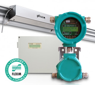
Ultrasonic Clamp-On Flowmeter with SIL 2 Rating

clamp on ultrasonic flowmeter with control unit SIL 2 rating
FLUXUS F/G70X and F/G80X series meters
Courtesy Flexim
Measuring the flow quantity of gases and liquids is a common industrial processing task. There are numerous technologies available for measuring fluid flow, each with its own set of advantages and drawbacks for any particular application. Some of the technologies and methods have been in use for a very long time, with recent enhancements provided by electronics or smart sensor designs.

Ultrasonic flow measurement devices employ a comparatively recent technology to measure gaseous or liquid flow. Whether the transit time differential or Doppler method is utilized, ultrasonic flow meters have a distinctive characteristic in that they can be deployed in a form factor that does not require insertion into the fluid. A common installation method is to clamp the ultrasonic transducer assembly onto the exterior of a pipe. This makes the technology attractive for applications that involve adding a flow measurement point to an existing piping system.

Flexim, a globally recognized leader in ultrasonic flow measurement, offers a number of permanent and portable units for measuring liquid and gaseous flow rates. Some of their instruments have been certified as SIL 2 capable, along with a host of other third party certifications. The product range includes simple and accurate instruments designed for general industrial use, and extends to multi-beam units intended for applications, such as custody transfer of fluids, that require the highest accuracy and overall performance levels.

Share your flow measurement challenges and requirements with instrumentation specialists, combining your own process knowledge and experience with their product application expertise to develop effective solutions.


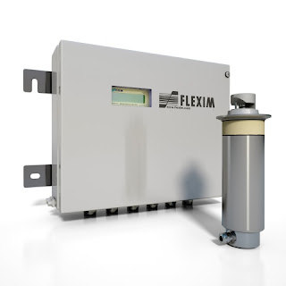
Inline Refractometers Used in Commercial Food and Beverage Production

in-line process refractometer with control housing
Hygienic process in-line refractometer
with control unit and flow cell
Courtesy Flexim
Refractometry is a measuring technique that evaluates the impact of fluid media on light. There are some variants of the basic technology, but essentially it relies upon the media affecting a change in the way in which light waves propagate through a sample. This refraction caused by the sample can be compared to a known standard and information about the sample can be deduced.

Refractometry is a useful measuring method for many liquid processing operations. It is used for concentration and density analysis of process liquids. Portable sample processing units are available, but high volume continuous flow operations benefit from the use of in-line refractometers that do not require manual sampling and handling of process liquids. The measurements are produced in real time to continuously verify the fluid quality characteristics.

Food and beverage manufacturers use refractometry to determine the concentration of sugar, ethanol, ascorbic acid, pectin, artificial sweeteners and other components in their products. Close control of component concentration is a necessary part of delivering a consistent taste in finished products. Large investments are made to establish brand name products, and delivery of a consistent customer experience each time a product is consumed is key to developing and growing a brand. This is a solid example of a marketing based application of science and technology to industrial processing.

In-line refractometers for food and beverage applications will have specific features and construction to make them suitable for hygienic processing. The avoidance of contamination is first and foremost a requirement. Additionally, design features that reduce maintenance requirements and retain the needed measuring accuracy through extended periods of usage add value to the unit and should be a consideration when selecting an in-line refractometer.

Share your in-line refractometry applications and challenges with product specialists, combining your process experience and knowledge with their product application expertise to develop effective solutions.


Simplex vs. Duplex Strainers For Industrial Liquid Processing

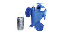
duplex basket strainer
Duplex basket strainer, shown with one basket removed
Courtesy Eaton Friltration
Many industrial and commercial liquid systems have mechanical components that cannot tolerate particulate matter in the liquid. Pumps, valves, sensors, and other specialties can experience accelerated wear and tear due to certain types and sizes of particulate matter.

Good practice dictates that the tolerance of the system for particulate matter should be determined and a properly sized and configured device be put in place to remove particulates larger than greatest allowable size. Considerations for connection size and type, construction material suitability for the process media, flow rate, pressure drop, and filter holding capacity should all be a part of the product selection criteria.

simplex basket strainer with basket removed
Simplex basket strainer with access cover and basket removed
Courtesy Eaton Filtration
One key element of the selection criteria is whether the system can be temporarily shut down for replacement or cleaning of the filtration element. A basket strainer, one of several types of liquid filtration devices, is available in both simplex and duplex variants. A simplex basket strainer functions as a single unit, requiring flow stoppage when the basket becomes clogged with debris. The changeover time may not be long, but some processes cannot tolerate any downtime. A duplex strainer is comprised of two simplex strainers, incorporated into a common housing, with an inlet chamber and diverting valve that selects which strainer basket will process the liquid flow. Changes in pressure drop through the device can be used to signal when it is time to switch operation between the strainer baskets.

Fluid filtration can be an important part of keeping a process in operation, reducing wear and tear on piping system components and equipment. Share your process fluid filtration challenges and requirements with application specialists, combining your process knowledge and experience with their product application expertise to produce effective solutions.

Hybrid Solar TEG Power Systems

hybrid solar PV photovoltaic thermoelectric generator TEG power system
Hybrid system shown in remote installation
Courtesy Gentherm Global Power Technologies
There are remotely located instruments and equipment throughout the world in places without available grid power. A suitable and reliable means to provide electric power is required as a standalone system for each of these instances. Photovoltaics is an obvious choice for power source, but there is another option that may provide substantial benefit for many installations.

A hybrid solar TEG (thermoelectric generator) can overcome some of the shortcomings of a pure PV system by delivering battery charging current during conditions when solar generated power is insufficient. The TEG uses heat from burning fuel to produce electric power, and can deliver charging current when the PV portion of the system fails to provide sufficient output.

  • Extended periods of bad weather. While this scenario can be compensated for with a larger battery array, there is still a limit to the performance period. Larger battery banks increase unit cost, size and weight.
  • Extreme low temperature. Battery capacity decreases during cold weather, requiring a larger battery array to provide design power output and reserve.
  • Low solar exposure during certain times of the year, requiring more solar panels to accomodate the system power requirements during times of reduced sunlight. This increases unit size and capital cost.

Critical power systems must be designed to deliver sufficient power under all environmental conditions that can be experienced at the installation site. This drives pure PV system designers to substantially oversize panel and battery arrays to assure power delivery throughout an entire year. A hybrid solar TEG system does not need to have the enormous headroom built into the design that a pure PV does. The TEG can produce power at a known rate, regardless of the surrounding environmental conditions. The potential benefits from the hybrid power system include: 

  • Reduction in solar panel array size and cost
  • Lower battery count, with reduction in capital cost, replacement cost, unit size and weight
  • Longer battery life
  • Less on-site fuel vs. a conventional fuel-based system
  • No more than once-per-year maintenance visits
  • Increased reliability over a pure PV installation

Share your remote installation power requirements and challenges with a product application specialist and bring the benefits of a hybrid solar TEG power system to your operation.


Switching Inductive Loads With Relays and Solid State Devices in Process Control

control panel interior process automation and control panel
Switching devices must be properly protected for longevity
We connect a lot of black boxes together in our control systems, not really knowing what goes on inside. There is a basic understanding of function, but maybe not enough knowledge to thoroughly assess all aspects of integrating a device into a train of control system components. We range from novice to seasoned expert, so Acromag, manufacturer and global supplier of I/O devices for process control, has provided a useful application note regarding the protection of devices employed to switch inductive loads.

The application paper provides a good explanation of what an inductive load is, and how it can impact the performance and longevity of a switching device. The document further explains how to offset the potentially damaging impact of an inductive load on a connected switching device, with specific examples and recommendations on how to put the protective measures in place. It is useful information.

The paper is provided below. Share your I/O and other process measurement and control challenges with application specialists, combining your own process knowledge with their product application expertise to develop effective solutions.


Selecting the Right Temperature, Pressure, or Differential Pressure Switch

industrial temperature switch pressure switch differential pressure switch
Temperature, pressure, and differential pressure switches come in a wide variety of configurations
Courtesy Ashcroft
Industrial process control applications present dynamic and varied requirements for measuring, monitoring and control. Each point calls for specific evaluation of the information needed from the process point for use in monitoring process performance, or control to be applied at the process point to regulate an outcome. Sometimes, a continuous analog signal is needed to provide indication across a range of values. Other times, it is only necessary to have notification of, or take action when, a certain temperature or pressure related event occurs. In those cases, a simple and reliable device can adequately meet the project requirements.

Temperature, pressure, and differential pressure switches connect to a process and change their switch position when a setpoint condition is reached. The are simple to understand, easy to install, low in cost, and require little maintenance of attention. The switches are available in an extensive array of configurations, with options to fill out almost any application requirement.

Ashcroft, global supplier of temperature and pressure switches, has produced a simplified guide that enables a designer or specifier to quickly focus their search on the right product. It is provided below for your use. Alternately, you can always share your process measurement and control requirements and challenges with product application specialists, combining your own process knowledge with their product expertise to develop effective solutions.


CSB Case Study of Industrial Plant Heat Exchanger Explosion

heat exchangers at industrial plant
Two heat exchangers at chemical plant
Industrial accidents, whether minor or catastrophic, can serve as sources of learning when analyzed and studied. Operators, owners, and technicians involved with industrial chemical operations have a degree of moral, ethical, and legal responsibility to conduct work in a reasonably and predictably safe manner without endangering personnel, property, or the environment. Part of a diligent safety culture should include reviewing industrial accidents at other facilities. There is much to learn from these unfortunate events, even when they happen in an industry that may seem somewhat removed from our own.

The U.S. Chemical Safety Board, or CSB, is an independent federal agency that investigates industrial chemical accidents. Below, find one of their video reenactments and analysis of an explosion that occurred at a Louisiana chemical processing plant in 2013. A portion of the reenactment shows how a few seemingly innocuous oversights can combine with other unrecognized conditions that result in a major conflagration.

Check out the video and sharpen your sense of awareness for potential trouble spots in your own operation.

Improved Level Measurement Contributes to Reduced Heat Rate in Steam Production

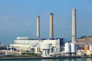
Power plant electrical generating plant
Minimizing heat rate and emissions for steam plants
Steam production is a costly operation in any facility, but is of paramount importance in power generation plants. The bottom line of a combustion based power generation facility is sensitive to the cost of input fuel. Measures that can be taken to reduce fuel input for a unit of power output (called heat rate) can translate directly into profitability. An additional benefit of reducing heat rate is a commensurate reduction in emissions.

A major contributor to heat rate reduction is the recovery of heat from the process and transference of that heat into the boiler feedwater. A sizable feedwater preheater of the shell and tube type is used to recover the heat. Shell and tube heat exchanger efficiency can be maximized with accurate control of liquid level.

Magnetrol, globally recognized leader in level measurement technology, makes the case for using guided wave radar level measurement technology as the most advantageous means for this application. The video below describes the process and how the guided wave radar level transmitter can provide the best performance.

Magnetrol has an information kit devoted to heat rate reduction. Share your steam system and level measurement challenges with a product specialist, and ask how you can get the Heat Rate Reduction Kit. Combining your facility and process knowledge with the product application expertise of a specialist will result in effective solutions.

M.S. Jacobs & Associates - Equipment Engineers

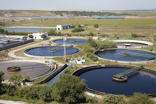
aerial view wastewater treatment plant settling ponds
Wastewater treatment is one of the many industrial sectors
served by M.S. Jacobs
M.S. Jacobs and Associates has been a leading manufacturer's representative and distributor of industrial instrumentation and controls since 1945. Expanding from its original focus on the steel industry, MS Jacobs services and supplies products in all major industrial markets, including power generation, chemical processing, pulp and paper, oil and gas production, water and wastewater treatment, and nuclear power generation.

The company's longevity and dedication to the industrial market has resulted in a broad offering of superior quality products for flow, level, pressure, and temperature measurement, as well as filtration products and valves. Everyone at MS Jacobs takes pride in the company's ability to solve tough applications and provide exceptional customer service with a team of trained outside sales engineers and inside customer service representatives.

MS Jacobs' Pittsburgh service center provides instrument calibration and repair for MSJ's complete line of products, as well as those of other manufacturers. The company carries factory authorization for repair of numerous manufacturers' industrial process instrumentation products. The service center also provides custom assembly of instruments and other gear to meet customer requirements. Completed assemblies are tested and certified prior to shipment.

Reach out to MS Jacobs & Associates for the products and services that move your process instrumentation and control projects toward a successful completion.


Self-Regulating Heat Trace for Freeze Protection

self-regulating heat cable heat trace
Example of self-regulating heating cable
Courtesy BriskHeat
Freeze protection is probably the most obvious application range for heat trace tape and cable. The applications are vast in number throughout the geographic region where real winter comes every year. Pipes, valves, tanks, vessels, conveyors and other equipment are all vulnerable to excessively cold conditions. Properly configured heating cable, blankets, or other shapes can reduce the risk of freezing liquids and keep protected items at safe operating temperatures.

Though freeze protection heating equipment and materials are available in many shapes, forms, and materials, this article will focus on self-regulating heating cable.

There are two basic types of heating cable. 


Constant wattage cable provides continuous full output whenever energized. It's application requires some means of limiting the temperature of the heated object. This can be a thermostat, or some other temperature controller and sensor combination. This simple on/off control is effective in many cases. More sophisticated arrangements can be accomplished with heater power controllers and a closed loop control system. The objective is to apply only as much heat (and energy) as necessary to prevent freezing or other cold induced undesirable conditions.

Self-regulating cable is designed and fabricated in a manner that reduces the heat output of the cable as its temperature increases, providing a built-in means of limiting applied heat without the need for any other means of control. Properly selected and installed heat cable of the self-regulating type will apply only the heat energy needed to maintain the desired condition. No other devices are required.

There are many heating solutions available for freeze protection to suit any application. Share your process heating and freeze protection challenges with product application specialists, combining your process knowledge and experience with their product application expertise to develop effective solutions.


Hinge Restrained Expansion Joints for Process Piping

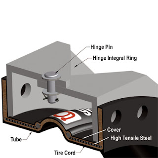
cutaway hinge restrained expansion joint for piping
Cutaway view of hinge restrained expansion joint
Process piping of sufficient size or extent can require allowances be made for expansion of the piping material in the installed location. The design criteria will include factors that impact the expansion of the piping components, as well as the relationships between the piping and elements of their supporting structures. Expansion can produce substantial movement of pipe sections which must be accommodated by the supports and the piping itself.

One manufacturer, General Rubber Corp., provides a hinge restrained rubber expansion joint that is designed to allow angular rotation of a piping section within a single plane. The expansion joint isolates the movement of one pipe section from its adjacent connected section. The assembly is comprised of a pair of pin connected hinge plates attached to the expansion joint hardware. The company further describes the unit construction and function...

The hinge assembly must be designed for the internal pressure thrust forces of the system. They can be used in sets of two or three to absorb large lateral movements in a single plane. This optimally designed arrangement is an effective solution for absorbing large axial thermal movements from an adjacent pipe run. Its spool type body is constructed with full rubber flanges, a high-grade leak proof-tube, multiple layers of high-strength tire cord, high tensile steel reinforcement and a seamless cover. They are commonly used when the support structure or adjacent equipment have load limitations. The economic benefits of this arrangement include a smaller system footprint with far fewer anchors and guides.
The video included below provides an animated illustration of how the expansion joint functions. More information is available from product specialists, with whom you should share your process piping system challenges.

Hazardous Gas and Flame Detection

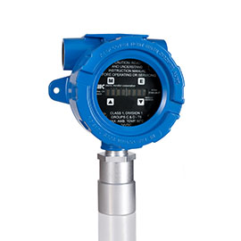
CO2 gas detector for industrial safety
Carbon dioxide level detector
Courtesy Sierra Monitor Corp.
MS Jacobs handles the Sierra Monitor line of gas and flame detection devices for use in commercial and industrial facilities. SMC manufactures complete solutions for gas and flame detection, from the sensors to the monitoring and control stations. The systems approach includes sensor modules, controllers, and software working together to provide detection, alarm, analytics, and delivery of all necessary information across communications networks.

SMC employs a variety of technologies to provide application matched performance in their gas and flame detectors. The company innovates and leverages their IIoT (Industrial Internet of Things) expertise to bring operating efficiency and enhanced levels of protection to customer facilities. Systems are tailored to provide the level of protection appropriate for a facility or application, as well as a customized response.

The various sensor  modules are optimized for their intended application range, bringing accuracy and efficiency to hazardous gas and flame detection. Some of the benefits include:

  • Low power requirements
  • Rapid response
  • Various filtering means to discriminate between noise and real hazards
  • Multiple output options that include relays, analog, and digital communications
  • Long calibration intervals for reduced maintenance
  • Remote sensor configuration
  • Self diagnostics
  • Local display
  • More
Share your gas and flame monitoring challenges with application specialists, combining your process and facility knowledge with their product application expertise to develop a comprehensive and effective solution.

Niagara Meters: Overview of Flow Measurement Devices

external view cutaway view target flowmeter
Cutaway and exterior views of target flowmeter
Niagara Meters, based in Spartanburg, South Carolina, is a well recognized brand in the flow measurement field. For over a hundred and fifty years, their products have been used in a myriad of industries, including agriculture, petrochemical processing, and even aboard United States Navy ships. The company’s flow meter products target three basic functions: flow measurement of liquid, gas flowmeters, and flowmeters for steam. The three product application groups are anchored by Niagara’s operating technology thesis statement, “specializing in innovative, reliable products.”

The largest array of Niagara meters are those utilized for liquid flow measurement. For measuring liquid in an open channel, such as a weir or flume, Niagara offers an application specific ultrasonic open channel flowmeter, which comes equipped with one or more sensors, along with a level monitor. The device is flexibly configurable for different arrays, and calculates liquid level, open channel flow and differential level measurement.

cutaway view turbine flowmeter
Cutaway view of turbine flowmeter
Measuring potable water flow through a pipe branch or system can be accomplished easily with the reliable mechanical MTX/WPX model series. In this turbine technology flowmeter, water pressure and resulting flow drives the internal turbine rotor. Magnetic coupling of the rotor to a flow indicator makes this instrument simple, reliable, and rugged for totalizing, rate of flow, and batch control applications.

Flow measurement in applications involving liquids with viscosity similar to oil are candidates for Niagara’s positive displacement oscillating piston flowmeter. This positive displacement device employs a piston which rotates in a flow chamber inside the meter. Liquid flow forces the piston to rotate, with the rotations recorded by a totalizer or pulse transmitter. Mechanical and smart electronic versions are available in a number of variants to meet the range of register and interface requirements.

Another mechanical positive displacement technology from the company uses a nutating disc and gear train to measure flow and provide a totalized flow register. The nutating disc is precisely fitted into the flow chamber and wobbles in a predictable manner that can be counted and used to measure volumetric flow. As with the oscillating piston products, a wide array of variants, including a smart meter version, are available to accommodate any register requirement.

Niagara also offers a fully electronic magnetic flowmeter, or Magmeter. The 6600 Series Magmeter can only be applied with conductive fluids, and converts the voltage produced when the fluid flows through a magnetic field to a volumetric flow signal for a high accuracy solution with no moving parts.

The company offers one additional category of flowmeter technology; applicable to liquids, gas, or steam. The target meter has a solid disk (the target) located in the flow path. The dynamic force of fluid movement acting on the target is converted to an electrical output signal that is proportional to flow rate.

All of Niagara’s flow measurement devices are time proven through many applications. For assistance in selecting and configuring a flowmeter for a particular application, share your requirements and process measurement challenges with a product specialist. The combination of your process knowledge and their product application expertise will produce effective solutions.

Float and Thermostatic Steam Traps

Float and thermostatic steam trap
Float and Thermostatic Steam Trap
Courtesy Colton Industries
Steam traps are found on almost every steam system in commercial and industrial sites. The trap is a self-contained automatic valve that allows condensate to drain from a steam containing system, while retaining the steam within the system. Non-condensible gases can also be removed by a steam trap with a thermostatically controlled port.

Steam based heating relies on the delivery of the latent heat of the steam to a heat exchanger or piece of utilization equipment. Once the latent heat is delivered, condensate (basically hot water) forms. The condensate contains no latent heat and provides comparatively little value as a heat source. Utilization equipment and heat exchangers have their performance predicated upon a supply of steam, not hot water. A properly selected steam trap will remove condensate across a range of steam utilization rates, keeping the system operating at the rated capacity.

The steam trap routes the condensate out of the steam containing portion of the system, often on a return trip to the boiler. Cycling the condensate back through the system for re-boiling contributes greatly to steam system energy efficiency. Condensate removal is accomplished with a float. Non-condensible gases are vented through a thermostatically controlled port on the unit.

More details on steam traps are included below. Share your steam system challenges with a product specialist, combining your facility and process knowledge with their product application expertise to develop effective solutions.